
Chapter 12
Hydraulic & Pneumatic Power Systems
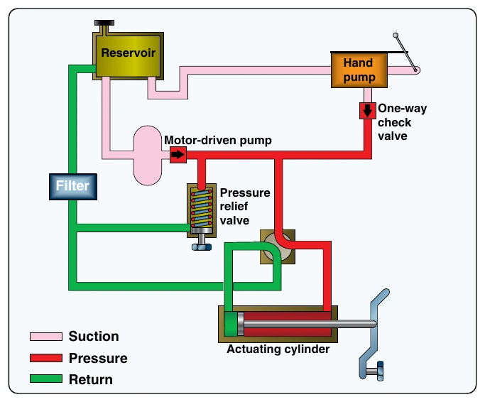
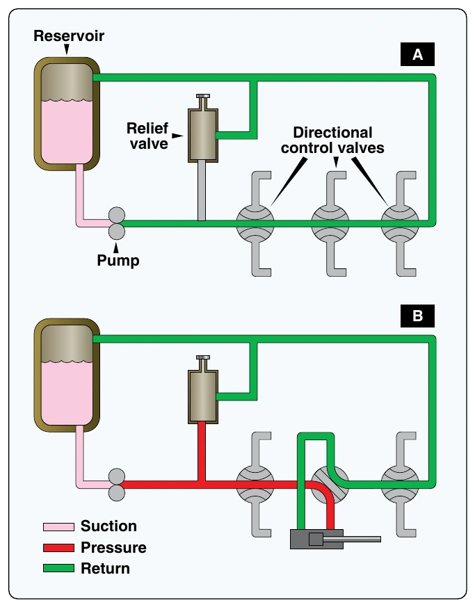
Several types of selector valves are used in conjunction with the open center system. One type is both manually engaged and manually disengaged. First, the valve is manually moved to an operating position. Then, the actuating mechanism reaches the end of its operating cycle, and the pump output continues until the system relief valve relieves the pressure. The relief valve unseats and allows the fluid to flow back to the reservoir. The system pressure remains at the relief valve set pressure until the selector valve is manually returned to the neutral position. This action reopens the open center flow and allows the system pressure to drop to line resistance pressure.
The manually engaged and pressure disengaged type of selector valve is similar to the valve previously discussed. When the actuating mechanism reaches the end of its cycle, the pressure continues to rise to a predetermined pressure. The valve automatically returns to the neutral position and to open center flow.
Closed-Center Hydraulic Systems
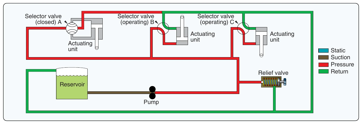
In the closed-center system, the fluid is under pressure whenever the power pump is operating. The three actuators are arranged in parallel and actuating units B and C are operating at the same time, while actuating unit A is not operating. This system differs from the open-center system in that the selector or directional control valves are arranged in parallel and not in series. The means of controlling pump pressure varies in the closed-center system. If a constant delivery pump is used, the system pressure is regulated by a pressure regulator. A relief valve acts as a backup safety device in case the regulator fails.
If a variable displacement pump is used, system pressure is controlled by the pump’s integral pressure mechanism compensator. The compensator automatically varies the volume output. When pressure approaches normal system pressure, the compensator begins to reduce the flow output of the pump. The pump is fully compensated (near zero flow) when normal system pressure is attained. When the pump is in this fully compensated condition, its internal bypass mechanism provides fluid circulation through the pump for cooling and lubrication. A relief valve is installed in the system as a safety backup. [Figure 12-4] An advantage of the open-center system over the closed-center system is that the continuous pressurization of the system is eliminated. Since the pressure is built up gradually after the selector valve is moved to an operating position, there is very little shock from pressure surges. This action provides a smoother operation of the actuating mechanisms. The operation is slower than the closed-center system, in which the pressure is available the moment the selector valve is positioned. Since most aircraft applications require instantaneous operation, closed-center systems are the most widely used.
Hydraulic Power Systems
Evolution of Hydraulic Systems
Smaller aircraft have relatively low flight control surface loads, and the pilot can operate the flight controls by hand.
Hydraulic systems were utilized for brake systems on early aircraft. When aircraft started to fly faster and got larger in size, the pilot was not able to move the control surfaces by hand anymore, and hydraulic power boost systems were introduced. Power boost systems assist the pilot in overcoming high control forces, but the pilot still actuates the flight controls by cable or push rod.
Many modern aircraft use a power supply system and fly-by-wire flight control. The pilot input is electronically sent to the flight control servos. Cables or push rods are not used. Small power packs are the latest evolution of the hydraulic system. They reduce weight by eliminating hydraulic lines and large quantities of hydraulic fluid. Some manufacturers are reducing hydraulic systems in their aircraft in favor of electrically controlled systems. The Boeing 787 is the first aircraft designed with more electrical systems than hydraulic systems.
Hydraulic Power Pack System
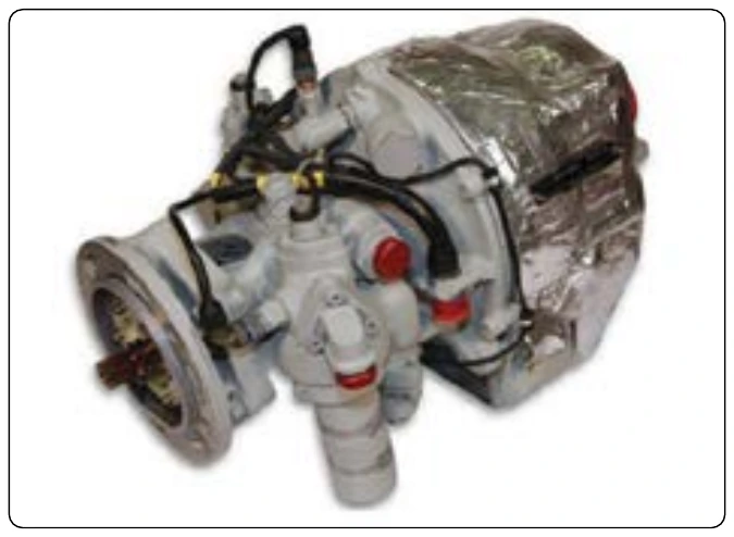
A hydraulic power pack is a small unit that consists of an electric pump, filters, reservoir, valves, and pressure relief valve. [Figure 12-5] The advantage of the power pack is that there is no need for a centralized hydraulic power supply system and long stretches of hydraulic lines, which reduces weight. Power packs could be driven by either an engine gearbox or electric motor. Integration of essential valves, filters, sensors, and transducers reduces system weight, virtually eliminates any opportunity for external leakage, and simplifies troubleshooting. Some power pack systems have an integrated actuator. These systems are used to control the stabilizer trim, landing gear, or flight control surfaces directly, thus eliminating the need for a centralized hydraulic system.
Hydraulic System Components
Figure 12-6 is a typical example of a hydraulic system in a large commercial aircraft. The following sections discuss the components of such system in more detail.
Reservoirs
The reservoir is a tank in which an adequate supply of fluid for the system is stored. Fluid flows from the reservoir to the pump, where it is forced through the system and eventually returned to the reservoir. The reservoir not only supplies the operating needs of the system, but it also replenishes fluid lost through leakage. Furthermore, the reservoir serves as an overflow basin for excess fluid forced out of the system by thermal expansion (the increase of fluid volume caused by temperature changes), the accumulators, and by piston and rod displacement.