
Chapter 12
Hydraulic & Pneumatic Power Systems
A manual bleeder valve is incorporated into the module. During hydraulic system maintenance, it is necessary to relieve reservoir air pressure to assist in the installation and removal of components, lines, etc. This type of valve is small in size and has a push button installed in the outer case. When the bleeder valve push button is pushed, pressurized air from the reservoir flows through the valve to an overboard vent until the air pressure is depleted or the button is released. When the button is released, the internal spring causes the poppet to return to its seat. Some hydraulic fluid can escape from the manual bleed valve when the button is depressed.
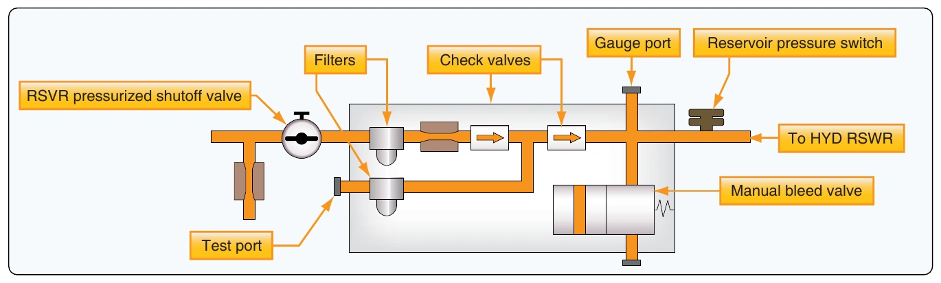
Caution: Put a rag around the air bleed valve on the reservoir pressurization module to catch hydraulic fluid spray. Hydraulic fluid spray can cause injuries to persons.
Fluid-Pressurized Reservoirs
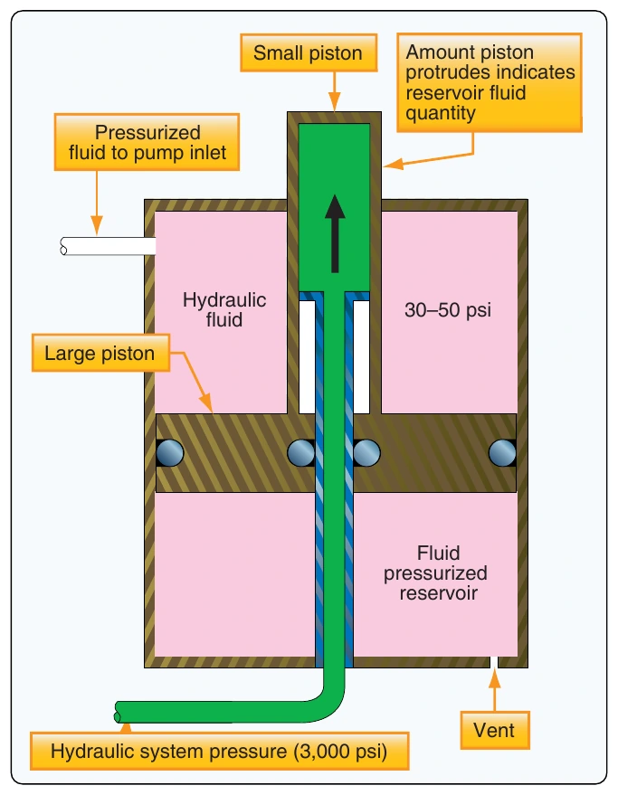
Some aircraft hydraulic system reservoirs are pressurized by hydraulic system pressure. Regulated hydraulic pump output pressure is applied to a movable piston inside the cylindrical reservoir. This small piston is attached to and moves a larger piston against the reservoir fluid. The reduced force of the small piston when applied by the larger piston is adequate to provide head pressure for high altitude operation. The small piston protrudes out of the body of the reservoir. The amount exposed is used as a reservoir fluid quantity indicator. Figure 12-13 illustrates the concept behind the fluid-pressurized hydraulic reservoir.
The reservoir has five ports: pump suction, return, pressurizing, overboard drain, and bleed port. Fluid is supplied to the pump through the pump suction port. Fluid returns to the reservoir from the system through the return port. Pressure from the pump enters the pressurizing cylinder in the top of the reservoir through the pressurizing port. The overboard drain port drains the reservoir, when necessary, while performing maintenance. The bleed port is used as an aid in servicing the reservoir. When servicing a system equipped with this type of reservoir, place a container under the bleed drain port. The fluid should then be pumped into the reservoir until air-free fluid flows through the bleed drain port.
The reservoir fluid level is indicated by the markings on the part of the pressurizing cylinder that moves through the reservoir dust cover assembly. There are three fluid level markings indicated on the cover: full at zero system pressure (FULL ZERO PRESS), full when system is pressurized (FULL SYS PRESS), and REFILL. When the system is unpressurized and the pointer on the reservoir lies between the two full marks, a marginal reservoir fluid level is indicated. When the system is pressurized, and the pointer lies between REFILL and FULL SYS PRESS, a marginal reservoir fluid level is also indicated.
Reservoir Servicing
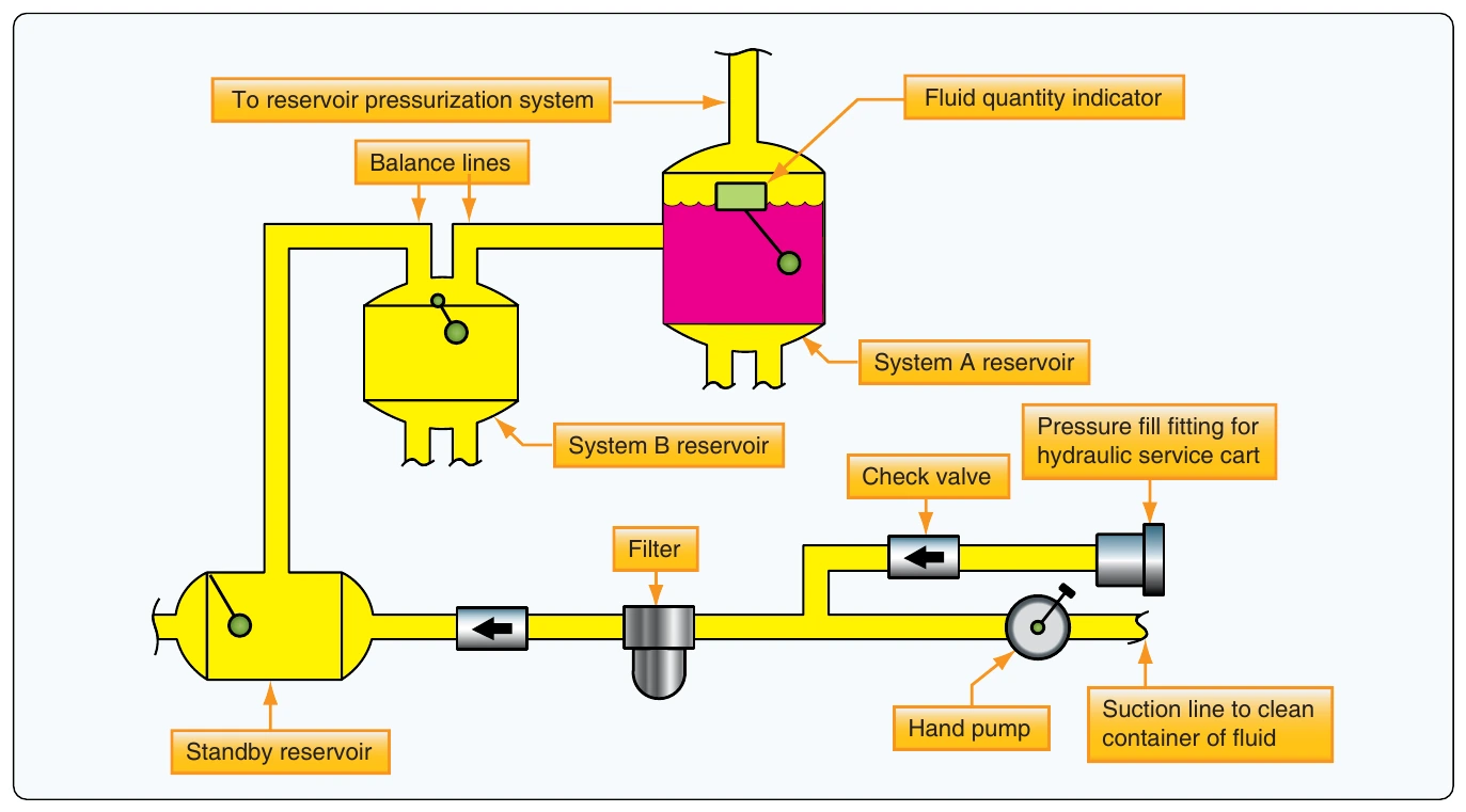
Nonpressurized reservoirs can be serviced by pouring fluid directly into the reservoir through a filler strainer (finger strainer) assembly incorporated within the filler well to strain out impurities as the fluid enters the reservoir. Many reservoirs also have a quick disconnect service port at the bottom of the reservoir. A hydraulic filler unit can be connected to the service port to add fluid to the reservoir. This method reduces the chances of contamination of the reservoir. Aircraft that use pressurized reservoirs often have a central filling station in the ground service bay to service all reservoirs from a single point. [Figure 12-14]
A built-in hand pump is available to draw fluid from a container through a suction line and pump it into the reservoirs. Additionally, a pressure fill port is available for attachment of a hydraulic mule or serving cart, which uses an external pump to push fluid into the aircraft hydraulic system. A check valve keeps the hand pump output from exiting the pressure fill port. A single filter is located downstream of both the pressure fill port and the hand pump to prevent the introduction of contaminants during fluid servicing.
It is very important to follow the maintenance instructions when servicing the reservoir. To get the correct results when the hydraulic fluid quantities are checked, or the reservoirs are to be filled, the airplane should be in the correct configuration. Failure to do so could result in overservicing of the reservoir. This configuration could be different for each aircraft. The following service instructions are an example of a large transport-type aircraft.
Before servicing always make sure that the:
- Spoilers are retracted,
- Landing gear is down,
- Landing gear doors are closed,
- Thrust reversers are retracted, and
- Parking brake accumulator pressure reads at least 2,500 psi.
Filters
A filter is a screening or straining device used to clean the hydraulic fluid, preventing foreign particles and contaminating substances from remaining in the system. [Figure 12-15] If such objectionable material were not removed, the entire hydraulic system of the aircraft could fail through the breakdown or malfunctioning of a single unit of the system.
The hydraulic fluid holds in suspension tiny particles of metal that are deposited during the normal wear of selector valves, pumps, and other system components. Such minute particles of metal may damage the units and parts through which they pass if they are not removed by a filter. Since tolerances within the hydraulic system components are quite small, it is apparent that the reliability and efficiency of the entire system depends upon adequate filtering.
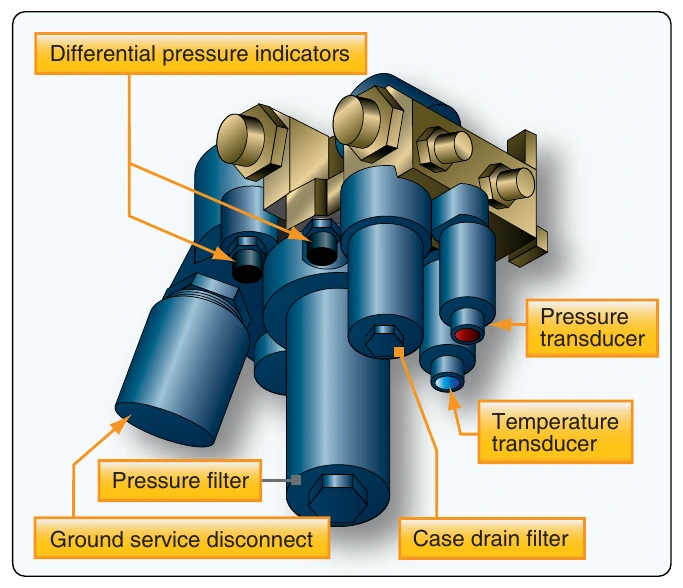
Filters may be located within the reservoir, in the pressure line, in the return line, or in any other location the designer of the system decides that they are needed to safeguard the hydraulic system against impurities. Modern design often uses a filter module that contains several filters and other components. [Figure 12-16] There are many models and styles of filters. Their position in the aircraft and design requirements determine their shape and size. Most filters used in modern aircraft are of the inline type. The inline filter assembly is comprised of three basic units: head assembly, bowl, and element. The head assembly is secured to the aircraft structure and connecting lines. Within the head, there is a bypass valve that routes the hydraulic fluid directly from the inlet to the outlet port if the filter element becomes clogged with foreign matter. The bowl is the housing that holds the element to the filter head and is removed when element removal is required.