
Chapter 12
Hydraulic & Pneumatic Power Systems
The reservoir also furnishes a place for the fluid to purge itself of air bubbles that may enter the system. Foreign matter picked up in the system may also be separated from the fluid in the reservoir or as it flows through line filters. Reservoirs are either pressurized or nonpressurized.
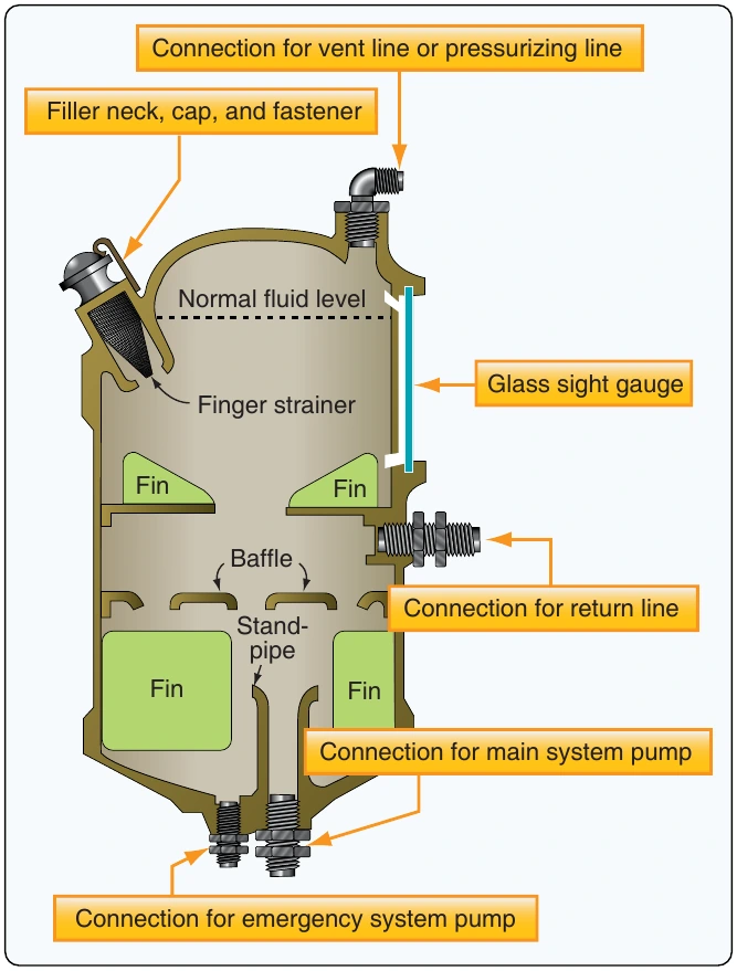
Baffles and/or fins are incorporated in most reservoirs to keep the fluid within the reservoir from having random movement, such as vortexing (swirling) and surging. These conditions can cause fluid to foam and air to enter the pump along with the fluid. Many reservoirs incorporate strainers in the filler neck to prevent the entry of foreign matter during servicing. These strainers are made of fine mesh screening and are usually referred to as finger strainers because of their shape. Finger strainers should never be removed or punctured as a means of speeding up the pouring of fluid into the reservoir. Reservoirs could have an internal trap to make sure fluid goes to the pumps during negative-G conditions.
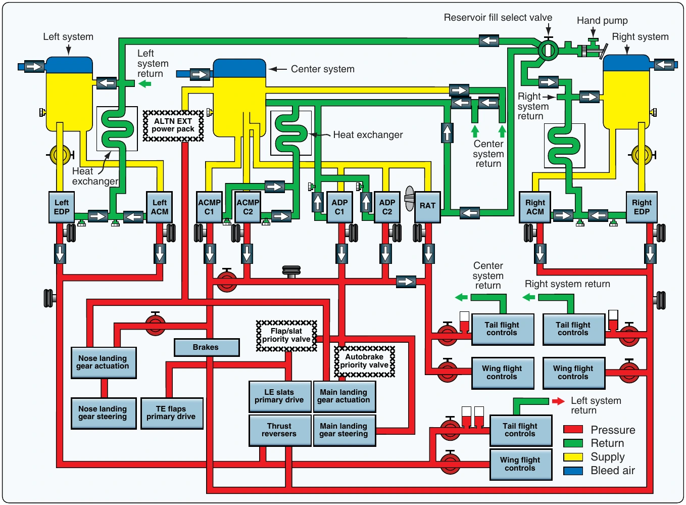
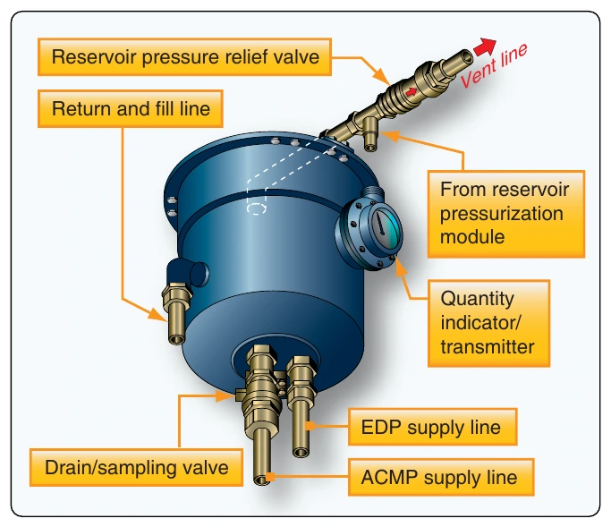
Most aircraft have emergency hydraulic systems that take over if main systems fail. In many such systems, the pumps of both systems obtain fluid from a single reservoir. Under such circumstances, a supply of fluid for the emergency pump is ensured by drawing the hydraulic fluid from the bottom of the reservoir. The main system draws its fluid through a standpipe located at a higher level. With this arrangement, should the main system’s fluid supply become depleted, adequate fluid is left for operation of the emergency system. Figure 12-7 illustrates that the engine-driven pump (EDP) is not able to draw fluid any more if the reservoir gets depleted below the standpipe. The alternating current motor-driven pump (ACMP) still has a supply of fluid for emergency operations.
Nonpressurized Reservoirs
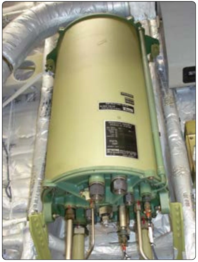
Nonpressurized reservoirs are used in aircraft that are not designed for violent maneuvers, do not fly at high altitudes, or in which the reservoir is located in the pressurized area of the aircraft. High altitude in this situation means an altitude where atmospheric pressure is inadequate to maintain sufficient flow of fluid to the hydraulic pumps. Most nonpressurized reservoirs are constructed in a cylindrical shape. The outer housing is manufactured from a strong corrosion-resistant metal. Filter elements are normally installed within the reservoir to clean returning system hydraulic fluid.
In some of the older aircraft, a filter bypass valve is incorporated to allow fluid to bypass the filter in the event the filter becomes clogged. Reservoirs can be serviced by pouring fluid directly into the reservoir through a filler strainer (finger strainer) assembly incorporated within the filler well to strain out impurities as the fluid enters the reservoir. Generally, nonpressurized reservoirs use a visual gauge to indicate the fluid quantity. Gauges incorporated on or in the reservoir may be a direct reading glass tube-type or a float-type rod that is visible through a transparent dome. In some cases, the fluid quantity may also be read in the flight deck through the use of quantity transmitters. A typical nonpressurized reservoir is shown in Figure 12-8. This reservoir consists of a welded body and cover assembly clamped together. Gaskets are incorporated to seal against leakage between assemblies.
Nonpressurized reservoirs are slightly pressurized due to thermal expansion of fluid and the return of fluid to the reservoir from the main system. This pressure ensures that there is a positive flow of fluids to the inlet ports of the hydraulic pumps. Most reservoirs of this type are vented directly to the atmosphere or cabin with only a check valve and filter to control the outside air source. The reservoir system includes a pressure and vacuum relief valve. The purpose of the valve is to maintain a differential pressure range between the reservoir and cabin. A manual air bleed valve is installed on top of the reservoir to vent the reservoir. The valve is connected to the reservoir vent line to allow depressurization of the reservoir. The valve is actuated prior to servicing the reservoir to prevent fluid from being blown out of the filler as the cap is being removed. The manual bleed valve also needs to be actuated if hydraulic components need to be replaced.
Pressurized Reservoirs
Reservoirs on aircraft designed for high-altitude flight are usually pressurized. Pressurizing assures a positive flow of fluid to the pump at high altitudes when low atmospheric pressures are encountered. On some aircraft, the reservoir is pressurized by bleed air taken from the compressor section of the engine. On others, the reservoir may be pressurized by hydraulic system pressure.
Air-Pressurized Reservoirs
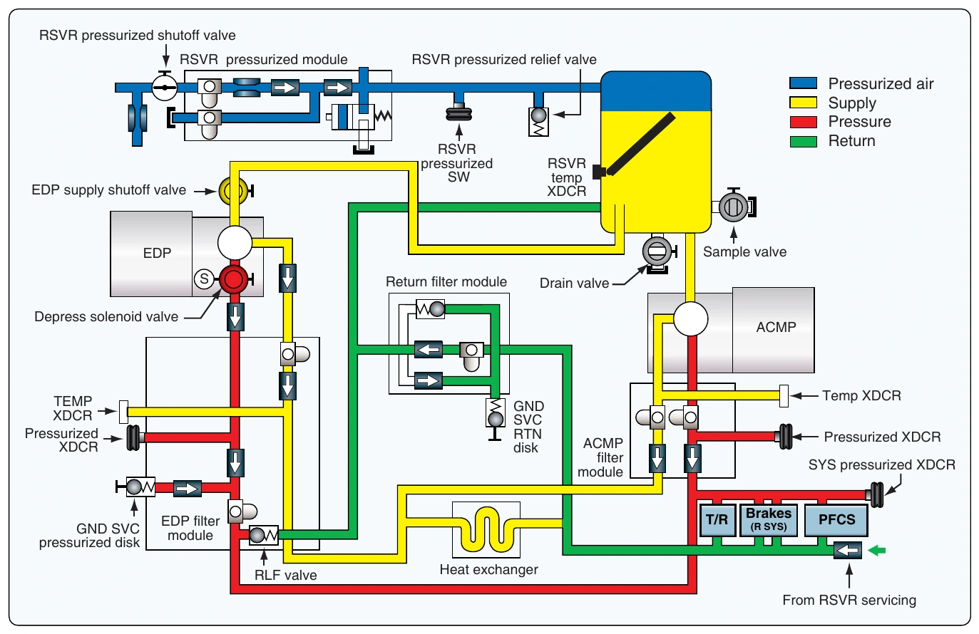
Air-pressurized reservoirs are used in many commercial transport-type aircraft. [Figures 12-9 and 12-10] Pressurization of the reservoir is required because the reservoirs are often located in wheel wells or other non-pressurized areas of the aircraft and at high altitude there is not enough atmospheric pressure to move the fluid to the pump inlet. Engine bleed air is used to pressurize the reservoir. The reservoirs are typically cylindrical in shape. The following components are installed on a typical reservoir:
- Reservoir pressure relief valve—prevents over pressurization of the reservoir. Valve opens at a preset value.
- Sight glasses (low and overfull)—provides visual indication for flight crews and maintenance personnel that the reservoir needs to be serviced.
- Reservoir sample valve—used to draw a sample of hydraulic fluid for testing.
- Reservoir drain valve—used to drain the fluids out of the reservoir for maintenance operation.
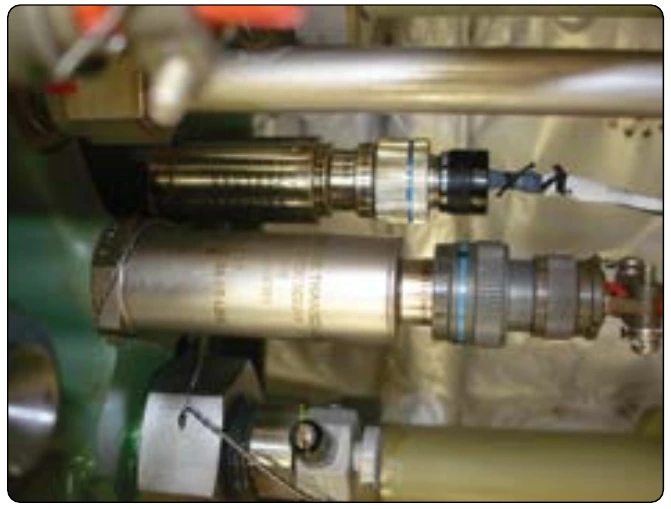
- Reservoir temperature transducer—provides hydraulic fluid temperature information for the flight deck. [Figure 12-11]
- Reservoir quantity transmitter—transmits fluid quantity to the flight deck so that the flight crew can monitor fluid quantity during flight. [Figure 12-11]
A reservoir pressurization module is installed close to the reservoir. [Figure 12-12] The reservoir pressurization module supplies airplane bleed air to the reservoirs. The module consists of the following parts:
- Filters (2).
- Check valves (2).
- Test port.
- Manual bleed valve.
- Gauge port.