Chapter 17
Fire Protection Systems
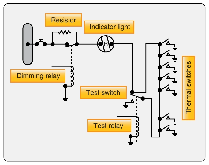
Some warning lights are push-to-test lights. The bulb is tested by pushing it in to check an auxiliary test circuit. The circuit shown in Figure 17-1 includes a test relay. With the relay contact in the position shown, there are two possible paths for current flow from the switches to the light. This is an additional safety feature. Energizing the test relay completes a series circuit and checks all the wiring and the light bulb. Also included in the circuit shown in Figure 17-1 is a dimming relay. By energizing the dimming relay, the circuit is altered to include a resistor in series with the light. In some installations, several circuits are wired through the dimming relay, and all the warning lights may be dimmed at the same time.
Thermocouple System
The thermocouple fire warning system operates on an entirely different principle from the thermal switch system. A thermocouple depends on the rate of temperature rise and does not give a warning when an engine slowly overheats or a short circuit develops. The system consists of a relay box, warning lights, and thermocouples. The wiring system of these units may be divided into the following circuits:
- Detector circuit.
- Alarm circuit.
- Test circuit.
These circuits are shown in Figure 17-2. The relay box contains two relays, the sensitive relay and the slave relay, and the thermal test unit. Such a box may contain from one to eight identical circuits, depending on the number of potential fire zones. The relays control the warning lights. In turn, the thermocouples control the operation of the relays. The circuit consists of several thermocouples in series with each other and with the sensitive relay.
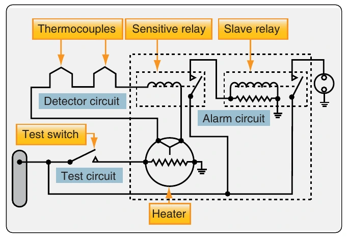
The thermocouple is constructed of two dissimilar metals, such as chromel and constantan. The point at which these metals are joined and exposed to the heat of a fire is called a hot junction. There is also a reference junction enclosed in a dead air space between two insulation blocks. A metal cage surrounds the thermocouple to give mechanical protection without hindering the free movement of air to the hot junction. If the temperature rises rapidly, the thermocouple produces a voltage because of the temperature difference between the reference junction and the hot junction. If both junctions are heated at the same rate, no voltage results. In the engine compartment, there is a normal, gradual rise in temperature from engine operation; because it is gradual, both junctions heat at the same rate and no warning signal is given. If there is a fire, however, the hot junction heats more rapidly than the reference junction. The ensuing voltage causes a current to flow within the detector circuit. Any time the current is greater than 4 milliamperes (0.004 ampere), the sensitive relay closes. This completes a circuit from the aircraft power system to the coil of the slave relay. The slave relay then closes and completes the circuit to the warning light to give a visual fire warning.
The total number of thermocouples used in individual detector circuits depends on the size of the fire zones and the total circuit resistance, which usually does not exceed 5 ohms. As shown in Figure 17-2, the circuit has two resistors. The resistor connected across the slave relay terminals absorbs the coil’s self-induced voltage to prevent arcing across the points of the sensitive relay. The contacts of the sensitive relay are so fragile that they burn, or weld, if arcing is permitted.
When the sensitive relay opens, the circuit to the slave relay is interrupted and the magnetic field around its coil collapses. The coil then gets a voltage through self-induction but, with the resistor across the coil terminals, there is a path for any current flow as a result of this voltage, eliminating arcing at the sensitive relay contacts.
Continuous-Loop Systems
Transport aircraft almost exclusively use continuous thermal sensing elements for powerplant and wheel well protection. These systems offer superior detection performance and coverage, and they have the proven ruggedness to survive in the harsh environment of modern turbofan engines.
A continuous-loop detector or sensing system permits more complete coverage of a fire hazard area than any of the spot-type temperature detectors. Two widely used types of continuous-loop systems are the thermistor type detectors, such as the Kidde and the Fenwal systems, and the pneumatic pressure detector, such as the Lingberg system. (Lindberg system is also known as Systron-Donner and, more recently, Meggitt Safety Systems.)
Fenwal System
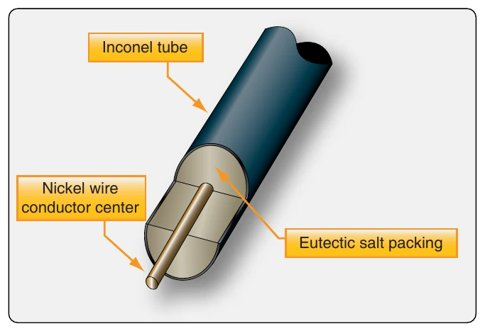
The Fenwal system uses a slender Inconel tube packed with thermally sensitive eutectic salt and a nickel wire center conductor. [Figure 17-3] Lengths of these sensing elements are connected in series to a control unit. The elements may be of equal or varying length and of the same or different temperature settings. The control unit, operating directly from the power source, impresses a small voltage on the sensing elements. When an overheat condition occurs at any point along the element length, the resistance of the eutectic salt within the sensing element drops sharply, causing current to flow between the outer sheath and the center conductor. This current flow is sensed by the control unit, which produces a signal to actuate the output relay and activate the alarms. When the fire has been extinguished or the critical temperature lowered below the set point, the Fenwal system automatically returns to standby alert, ready to detect any subsequent fire or overheat condition. The Fenwal system may be wired to employ a loop circuit. In this case, should an open circuit occur, the system still signals fire or overheat. If multiple open circuits occur, only that section between breaks becomes inoperative.
Kidde System
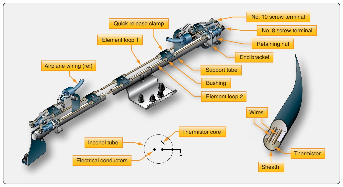
In the Kidde continuous-loop system, two wires are embedded in an Inconel tube filled with a thermistor core material. [Figure 17-4] Two electrical conductors go through the length of the core. One conductor has a ground connection to the tube, and the other conductor connects to the fire detection control unit. As the temperature of the core increases, electrical resistance to the ground decreases. The fire detection control unit monitors this resistance. If the resistance decreases to the overheat set point, an overheat indication occurs in the flight deck. Typically, a 10-second time delay is incorporated for the overheat indication. If the resistance decreases more to the fire set point, a fire warning occurs. When the fire or overheat condition is gone, the resistance of the core material increases to the reset point and the flight deck indications disappear. The rate of change of resistance identifies an electrical short or a fire. The resistance decreases more quickly with an electrical short than with a fire. In some aircraft, in addition to fire and overheat detection, the Kidde continuous-loop system can supply nacelle temperature data to the airplane condition monitoring function of the aircraft in-flight monitoring system (AIMS).