Chapter 17
Fire Protection Systems
The control unit for the simplest type of system typically contains the necessary electronic resistance monitoring and alarm output circuits housed in a hermetically sealed aluminum case fitted with a mounting bracket and electrical connector. For more sophisticated systems, control modules are employed that contain removable control cards with circuitry for individual hazard areas and/or unique functions. In the most advanced applications, the detection system circuitry controls all aircraft fire protection functions, including fire detection and extinguishing for engines, APUs, cargo bays, and bleed-air systems.
Pressure Type Sensor Responder Systems
Some smaller turboprop aircraft are outfitted with pneumatic single point detectors. The design of these detectors is based on the principles of gas laws. The sensing element consists of a closed, helium-filled tube connected at one end to a responder assembly. As the element is heated, the gas pressure inside the tube increases until the alarm threshold is reached. At this point, an internal switch closes and reports an alarm to the flight deck. Continuous fault monitoring is included. This type of sensor is designed as a single-sensor detection system and does not require a control unit.
Pneumatic Continuous-Loop Systems
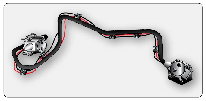
The pneumatic continuous-loop systems are also known by their manufacturers’ names Lindberg, Systron-Donner, and Meggitt Safety Systems. These systems are used for engine fire detection of transport type aircraft and have the same function as the Kidde system; however, they work on a different principle. They are typically used in a dual-loop design to increase reliability of the system.
The pneumatic detector has two sensing functions. It responds to an overall average temperature threshold and to a localized discrete temperature increase caused by impinging flame or hot gasses. Both the average and discrete temperature are factory set and are not field adjustable. [Figure 17-6]
Averaging Function
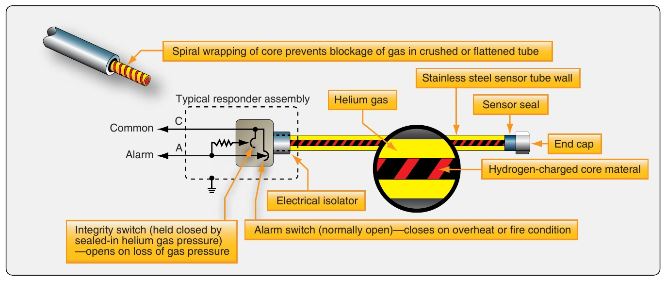
The fire/overheat detector serves as a fixed-volume device filled with helium gas. The helium gas pressure inside the detector increases in proportion to the absolute temperature and operates a pressure diaphragm that closes an electrical contact, actuating the alarm circuit. The pressure diaphragm within the responder assembly serves as one side of the electrical alarm contact and is the only moving part in the detector. The alarm switch is preset at an average temperature. Typical temperature ranges for average temperature settings are 200 °F (93 °C) to 850 °F (454 °C).
Discrete Function
The fire/overheat detector’s sensor tube also contains a hydrogen-filled core material. [Figure 17-7] Large quantities of hydrogen gas are released from the detector core whenever a small section of the tube is heated to the preset discrete temperature or higher. The core outgassing increases the pressure inside the detector and actuates the alarm switch. Both the averaging and discrete functions are reversible. When the sensor tube is cooled, the average gas pressure is lowered, and the discrete hydrogen gas returns to the core material. The reduction of internal pressure allows the alarm switch to return to its normal position, opening the electrical alarm circuit.
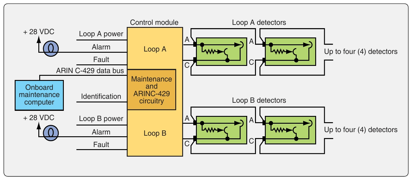
Figure 17-8 shows a typical aircraft fire detection system in which a control module monitors two loops of up to four pneumatic detectors each, connected in parallel. The control module responds directly to an alarm condition and continuously monitors the wiring and integrity of each loop. The normally open alarm switch closes upon an overheat or fire condition, causing a short circuit between terminals A and
- During normal operation, a resistance value is maintained across the terminals by a normally closed integrity switch.
Loss of sensor gas pressure opens the integrity switch, creating an open circuit across the terminals of the faulted detector. In addition to the pressure-activated alarm switch, there is a second integrity switch in the detector that is held closed by the averaging gas pressure at all temperatures down to –65 °F (–54 °C). If the detector should develop a leak, the loss of gas pressure would allow the integrity switch to open and signal a lack of detector integrity. The system then does not operate during test.
Fire Zones
Powerplant compartments are classified into zones based on the airflow through them.
- Class A zone—area of heavy airflow past regular arrangements of similarly shaped obstructions. The power section of a reciprocating engine is usually of this type.
- Class B zone—area of heavy airflow past aerodynamically clean obstructions. Included in this type are heat exchanger ducts, exhaust manifold shrouds, and areas where the inside of the enclosing cowling or other closure is smooth, free of pockets, and adequately drained so leaking flammables cannot puddle. Turbine engine compartments may be considered in this class if engine surfaces are aerodynamically clean and all airframe structural formers are covered by a fireproof liner to produce an aerodynamically clean enclosure surface.
- Class C zone—area of relatively low airflow. An engine accessory compartment separated from the power section is an example of this type of zone.
- Class D zone—area of very little or no airflow. These include wing compartments and wheel wells where little ventilation is provided.
- Class X zone—area of heavy airflow and of unusual construction, making uniform distribution of the extinguishing agent very difficult. Areas containing deeply recessed spaces and pockets between large structural formers are of this type. Tests indicate agent requirements to be double those for Class A zones.