
Chapter 17
Fire Protection Systems
The resistance of a sensor varies inversely as it is heated; as sensor temperature is increased, its resistance decreases. Each sensor is composed of two wires embedded in thermistor material that is encased in a heavy wall Inconel tube for high strength at elevated temperatures. The electrical connectors at each end of the sensor are ceramic insulated. The Inconel tubes are shrouded in a perforated stainless-steel tube and supported by Teflon-impregnated asbestos bushings at intervals. The shroud protects the sensor from breakage due to vibration, abrasion against airplane structure, and damage from maintenance activity.
The resistance of a sensor also varies inversely with its length, the increments of length being resistances in parallel. The heating of a short length of sensor out of a given length requires that the short length be heated above the temperature alarm point, so the total resistance of the sensor decreases to the alarm point. This characteristic permits integration of all temperatures throughout the length of the installation rather than sensing only the highest local temperature. The two wires encased within the thermistic material of each Inconel tube form a variable resistance network between themselves, between the detector wire and the Inconel tube, and between each adjacent incremental length of sensor. These variable resistance networks are monitored by the application of 28 volts direct current (DC) to the detector wire from the detector control unit.
Combination Fire & Overheat Warning
The analog signal from the thermistor-sensing element permits the control circuits to be arranged to give a two-level response from the same sensing element loop. The first is an overheat warning at a temperature level below the fire warning indicating a general engine compartment temperature rise, such as would be caused by leakage of hot bleed air or combustion gas into the engine compartment. It could also be an early warning of fire and would alert the crew to appropriate action to reduce the engine compartment temperature. The second-level response is at a level above that attainable by a leaking hot gas and is the fire warning.
Temperature Trend Indication
The analog signal produced by the sensing element loop as its temperature changes is converted to signals suitable for flight deck display to indicate engine bay temperature increases from normal. A comparison of the readings from each loop system also provides a check on the condition of the fire detection system, because the two loops should normally read alike.
System Test
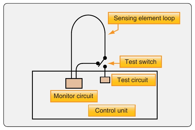
The integrity of the continuous-loop fire detection system may be tested by actuating a test switch in the flight deck that switches one end of the sensing element loop from its control circuit to a test circuit built into the control unit, which simulates the sensing element resistance change due to fire. [Figure 17-5] If the sensing element loop is unbroken, the resistance detected by the control circuit is that of the simulated fire, and the alarm is activated. The test demonstrates, in addition to the continuity of the sensing element loop, the integrity of the alarm indicator circuit and the proper functioning of the control circuits. The thermistic properties of the sensing element remain unchanged for the life of the element (no irreversible changes take place when heated); the element functions properly as long as it is electrically connected to the control unit.
Fault Indication
Provision is made in the control unit to output a fault signal which activates a fault indicator whenever the short discriminator circuit detects a short in the sensing element loop. This is a requirement for transport category aircraft because such a short disables the fire detection system.
Dual-Loop Systems
Dual-loop systems are two complete basic fire detection systems with their output signals connected so that both must signal to result in a fire warning. This arrangement, called AND logic, results in greatly increased reliability against false fire warnings from any cause. Should one of the two loops be found inoperative at the preflight integrity test, a flight deck selector switch disconnects that loop and allows the signal from the other loop alone to activate the fire warning. Since the single operative loop meets all fire detector requirements, the aircraft can be safely dispatched and maintenance deferred to a more convenient time. However, should one of the two loops become inoperative in flight and a fire subsequently occur, the fire signaling loop activates a flight deck fault signal that alerts the flight crew to select single-loop operation to confirm the possible occurrence of fire.
Automatic Self-Interrogation
Dual-loop systems automatically perform the loop switching and decision-making function required of the flight crew upon appearance of the fault indication in the flight deck, a function called automatic self-interrogation. Automatic self-interrogation eliminates the fault indication and assures the immediate appearance of the fire indication should fire occur while at least one loop of the dual-loop system is operative. Should the control circuit from a single-loop signal fire, the self-interrogation circuit automatically tests the functioning of the other loop. If it tests operative, the circuit suppresses the fire signal because the operative loop would have signaled if a fire existed. If, however, the other loop tests inoperative, the circuit outputs a fire signal. The interrogation and decision takes place in milliseconds, so that no delay occurs if a fire actually exists.
Support Tube Mounted Sensing Elements
For those installations where it is desired to mount the sensing elements on the engine, and in some cases, on the aircraft structure, the support tube mounted element solves the problem of providing sufficient element support points and greatly facilitates the removal and reinstallation of the sensing elements for engine or system maintenance.
Most modern installations use the support tube concept of mounting sensing elements for better maintainability, as well as increased reliability. The sensing element is attached to a prebent stainless steel tube by closely spaced clamps and bushings, where it is supported from vibration damage and protected from pinching and excessive bending. The support tube-mounted elements can be furnished with either single or dual sensing elements.
Being prebent to the designed configuration assures its installation in the aircraft precisely in its designed location, where it has the necessary clearance to be free from the possibility of the elements chafing against engine or aircraft structure. The assembly requires only a few attachment points and, should its removal for engine maintenance be necessary, it is quickly and easily accomplished. Should the assembly require repair or maintenance, it is easily replaced with another assembly, leaving the repair for the shop. Should a sensing element be damaged, it is easily replaced in the assembly.