
Chapter 2
Aerodynamics, Aircraft Assembly, & Rigging
Newton’s second law states that if a body moving with uniform speed is acted upon by an external force, the change of motion is proportional to the amount of the force, and motion takes place in the direction in which the force acts. This law may be stated mathematically as follows:
If an aircraft is flying against a headwind, it is slowed down. If the wind is coming from either side of the aircraft’s heading, the aircraft is pushed off course unless the pilot takes corrective action against the wind direction.
Newton’s third law is the law of action and reaction. This law states that for every action (force) there is an equal and opposite reaction (force). This law can be illustrated by the example of firing a gun. The action is the forward movement of the bullet while the reaction is the backward recoil of the gun.
The three laws of motion that have been discussed apply to the theory of flight. In many cases, all three laws may be operating on an aircraft at the same time.
Bernoulli’s Principle & Subsonic Flow
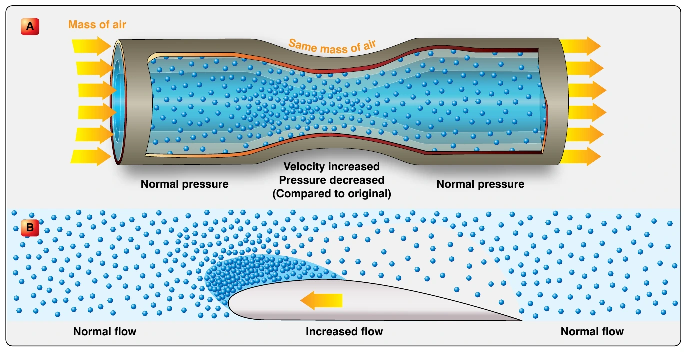
Bernoulli’s principle states that when a fluid (air) flowing through a tube reaches a constriction, or narrowing, of the tube, the speed of the fluid flowing through that constriction is increased and its pressure is decreased. The cambered (curved) surface of an airfoil (wing) affects the airflow exactly as a constriction in a tube affects airflow. [Figure 2-2] Diagram A of Figure 2-2 illustrates the effect of air passing through a constriction in a tube. In Diagram B, air is flowing past a cambered surface, such as an airfoil, and the effect is similar to that of air passing through a restriction.
As the air flows over the upper surface of an airfoil, its velocity increases and its pressure decreases; an area of low pressure is formed. There is an area of greater pressure on the lower surface of the airfoil, and this greater pressure tends to move the wing upward. The difference in pressure between the upper and lower surfaces of the wing is called lift. Three-fourths of the total lift of an airfoil is the result of the decrease in pressure over the upper surface. The impact of air on the under surface of an airfoil produces the other one-fourth of the total lift.
Airfoil
An airfoil is a surface designed to obtain lift from the air through which it moves. Thus, it can be stated that any part of the aircraft that converts air resistance into lift is an airfoil. The profile of a conventional wing is an excellent example of an airfoil. [Figure 2-3] Notice that the top surface of the wing profile has greater curvature than the lower surface.
The difference in curvature of the upper and lower surfaces of the wing builds up the lift force. Air flowing over the top surface of the wing must reach the trailing edge of the wing in the same amount of time as the air flowing under the wing. To do this, the air passing over the top surface moves at a greater velocity than the air passing below the wing because of the greater distance it must travel along the top surface. This increased velocity, according to Bernoulli’s Principle, means a corresponding decrease in pressure on the surface. Thus, a pressure differential is created between the upper and lower surfaces of the wing, forcing the wing upward in the direction of the lower pressure.
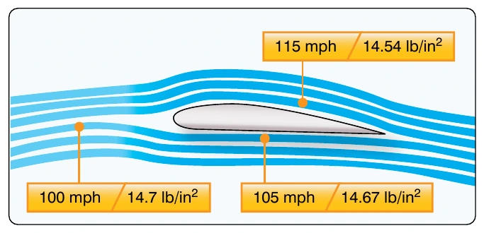
Within limits, lift can be increased by increasing the angle of attack (AOA), wing area, velocity, density of the air, or by changing the shape of the airfoil. When the force of lift on an aircraft’s wing equals the force of gravity, the aircraft maintains level flight.
Shape of the Airfoil
Individual airfoil section properties differ from those properties of the wing or aircraft as a whole because of the effect of the wing planform. A wing may have various airfoil sections from root to tip, with taper, twist, and sweepback.
The resulting aerodynamic properties of the wing are determined by the action of each section along the span.
The shape of the airfoil determines the amount of turbulence or skin friction that it produces, consequently affecting the efficiency of the wing. Turbulence and skin friction are controlled mainly by the fineness ratio, which is defined as the ratio of the chord of the airfoil to the maximum thickness. If the wing has a high fineness ratio, it is a very thin wing. Athick wing has a low fineness ratio. A wing with a high fineness ratio produces a large amount of skin friction. A wing with a low fineness ratio produces a large amount of turbulence. The best wing is a compromise between these two extremes to hold both turbulence and skin friction to a minimum.
The efficiency of a wing is measured in terms of the lift to drag ratio (L/D). This ratio varies with the AOA but reaches a definite maximum value for a particular AOA. At this angle, the wing has reached its maximum efficiency. The shape of the airfoil is the factor that determines the AOA at which the wing is most efficient; it also determines the degree of efficiency. Research has shown that the most efficient airfoils for general use have the maximum thickness occurring about one-third of the way back from the leading edge of the wing.
High-lift wings and high-lift devices for wings have been developed by shaping the airfoils to produce the desired effect. The amount of lift produced by an airfoil increases with an increase in wing camber. Camber refers to the curvature of an airfoil above and below the chord line surface. Upper camber refers to the upper surface, lower camber to the lower surface, and mean camber to the mean line of the section. Camber is positive when departure from the chord line is outward and negative when it is inward. Thus, high-lift wings have a large positive camber on the upper surface and a slightly negative camber on the lower surface. Wing flaps cause an ordinary wing to approximate this same condition by increasing the upper camber and by creating a negative lower camber.