
Chapter 2
Aerodynamics, Aircraft Assembly, & Rigging
It is also known that the larger the wingspan, as compared to the chord, the greater the lift obtained. This comparison is called aspect ratio. The higher the aspect ratio, the greater the lift. In spite of the benefits from an increase in aspect ratio, it was found that definite limitations were defined by structural and drag considerations.
On the other hand, an airfoil that is perfectly streamlined and offers little wind resistance sometimes does not have enough lifting power to take the aircraft off the ground. Thus, modern aircraft have airfoils which strike a medium between extremes, the shape depending on the purposes of the aircraft for which it is designed.
Angle of Incidence
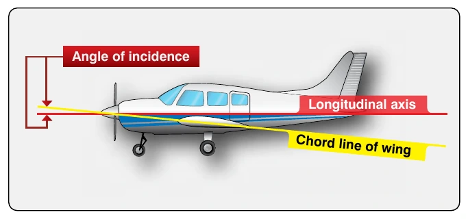
The acute angle the wing chord makes with the longitudinal axis of the aircraft is called the angle of incidence, or the angle of wing setting. [Figure 2-4] The angle of incidence in most cases is a fixed, built-in angle. When the leading edge of the wing is higher than the trailing edge, the angle of incidence is said to be positive. The angle of incidence is negative when the leading edge is lower than the trailing edge of the wing.
Angle of Attack (AOA)
Before beginning the discussion on AOA and its effect on airfoils, first consider the terms chord and center of pressure (CP) as illustrated in Figure 2-5.
The chord of an airfoil or wing section is an imaginary straight line that passes through the section from the leading edge to the trailing edge, as shown in Figure 2-5. The chord line provides one side of an angle that ultimately forms the AOA. The other side of the angle is formed by a line indicating the direction of the relative airstream. Thus, AOA is defined as the angle between the chord line of the wing and the direction of the relative wind. This is not to be confused with the angle of incidence, illustrated in Figure 2-4, which is the angle between the chord line of the wing and the longitudinal axis of the aircraft.
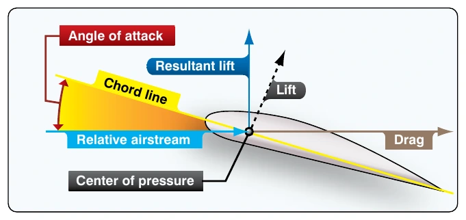
On each part of an airfoil or wing surface, a small force is present. This force is of a different magnitude and direction from any forces acting on other areas forward or rearward from this point. It is possible to add all of these small forces mathematically. That sum is called the “resultant force” (lift). This resultant force has magnitude, direction, and location, and can be represented as a vector, as shown in Figure 2-5. The point of intersection of the resultant force line with the chord line of the airfoil is called the center of pressure (CP). The CP moves along the airfoil chord as the AOA changes. Throughout most of the flight range, the CP moves forward with increasing AOA and rearward as theAOA decreases. The effect of increasing AOA on the CP is shown in Figure 2-6.
The AOA changes as the aircraft’s attitude changes. Since the AOA has a great deal to do with determining lift, it is given primary consideration when designing airfoils. In a properly designed airfoil, the lift increases as the AOA is increased. When the AOA is increased gradually toward a positive AOA, the lift component increases rapidly up to a certain point and then suddenly begins to drop off. During this action the drag component increases slowly at first, then rapidly as lift begins to drop off.
When the AOA increases to the angle of maximum lift, the burble point is reached. This is known as the critical angle. When the critical angle is reached, the air ceases to flow smoothly over the top surface of the airfoil and begins to burble or eddy. This means that air breaks away from the upper camber line of the wing. What was formerly the area of decreased pressure is now filled by this burbling air. When this occurs, the amount of lift drops and drag becomes excessive. The force of gravity exerts itself, and the nose of the aircraft drops. This is a stall. Thus, the burble point is the stalling angle.
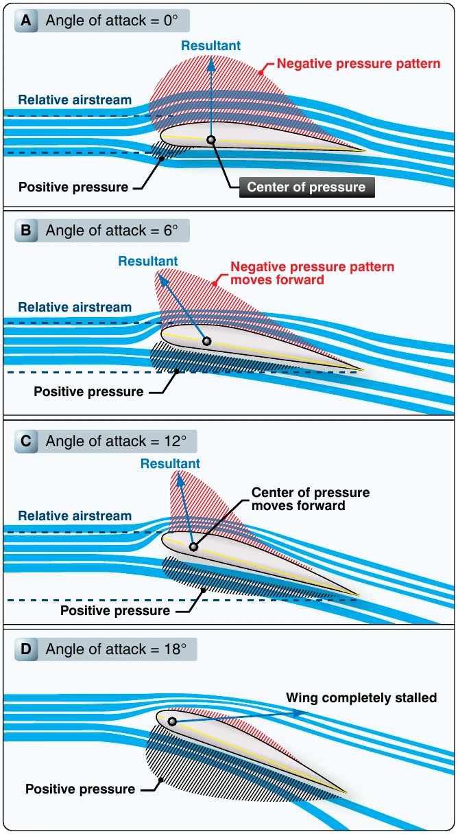
As previously seen, the distribution of the pressure forces over the airfoil varies with the AOA. The application of the resultant force, or CP, varies correspondingly. As this angle increases, the CP moves forward; as the angle decreases, the CP moves back. The unstable travel of the CP is characteristic of almost all airfoils.
Boundary Layer
In the study of physics and fluid mechanics, a boundary layer is that layer of fluid in the immediate vicinity of a bounding surface. In relation to an aircraft, the boundary layer is the part of the airflow closest to the surface of the aircraft. In designing high-performance aircraft, considerable attention is paid to controlling the behavior of the boundary layer to minimize pressure drag and skin friction drag.
Thrust & Drag
An aircraft in flight is the center of a continuous battle of forces. Actually, this conflict is not as violent as it sounds, but it is the key to all maneuvers performed in the air. There is nothing mysterious about these forces; they are definite and known. The directions in which they act can be calculated, and the aircraft itself is designed to take advantage of each of them. In all types of flying, flight calculations are based on the magnitude and direction of four forces: weight, lift, drag, and thrust. [Figure 2-7]
An aircraft in flight is acted upon by four forces:
- Gravity or weight—the force that pulls the aircraft toward the earth. Weight is the force of gravity acting downward upon everything that goes into the aircraft, such as the aircraft itself, crew, fuel, and cargo.
- Lift—the force that pushes the aircraft upward. Lift acts vertically and counteracts the effects of weight.
- Thrust—the force that moves the aircraft forward. Thrust is the forward force produced by the powerplant that overcomes the force of drag.
- Drag—the force that exerts a braking action to hold the aircraft back. Drag is a backward deterrent force and is caused by the disruption of the airflow by the wings, fuselage, and protruding objects.