Chapter 4
Aircraft Metal Structural Repair
Certain fundamental rules must be observed if the original strength of the structure is to be maintained.
Ensure that the cross-sectional area of a splice or patch is at least equal to or greater than that of the damaged part. Avoid abrupt changes in cross-sectional area. Eliminate dangerous stress concentration by tapering splices. To reduce the possibility of cracks starting from the corners of cutouts, try to make cutouts either circular or oval in shape. Where it is necessary to use a rectangular cutout, make the radius of curvature at each corner no smaller than 1⁄2-inch. If the member is subjected to compression or bending loads, the patch should be placed on the outside of the member to obtain a higher resistance to such loads. If the patch cannot be placed there, material one gauge thicker than the original shall be used for the repair.
Replace buckled or bent members or reinforce them by attaching a splice over the affected area. A buckled part of the structure shall not be depended upon to carry its load again, no matter how well the part may be strengthened.
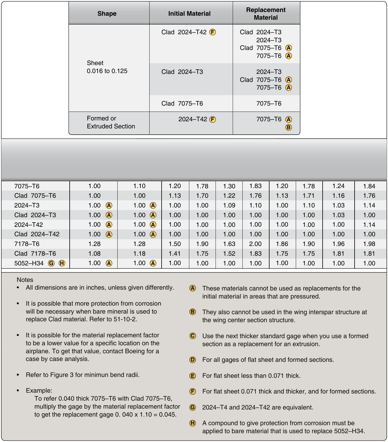
The material used in all replacements or reinforcements must be similar to that used in the original structure. If an alloy weaker than the original must be substituted for it, a heavier thickness must be used to give equivalent cross-sectional strength. A material that is stronger, but thinner, cannot be substituted for the original because one material can have greater tensile strength but less compressive strength than another, or vice versa. Also, the buckling and torsional strength of many sheet metal and tubular parts depends primarily on the thickness of the material rather than its allowable compressive and shear strengths. The manufacturer’s SRM often indicates what material can be used as a substitution and how much thicker the material needs to be. Figure 4-168 is an example of a substitution table found in an SRM.
Care must be taken when forming. Heat-treated and cold-worked aluminum alloys stand very little bending without cracking. On the other hand, soft alloys are easily formed, but they are not strong enough for primary structure. Strong alloys can be formed in their annealed (heated and allowed to cool slowly) condition, and heat treated before assembling to develop their strength.
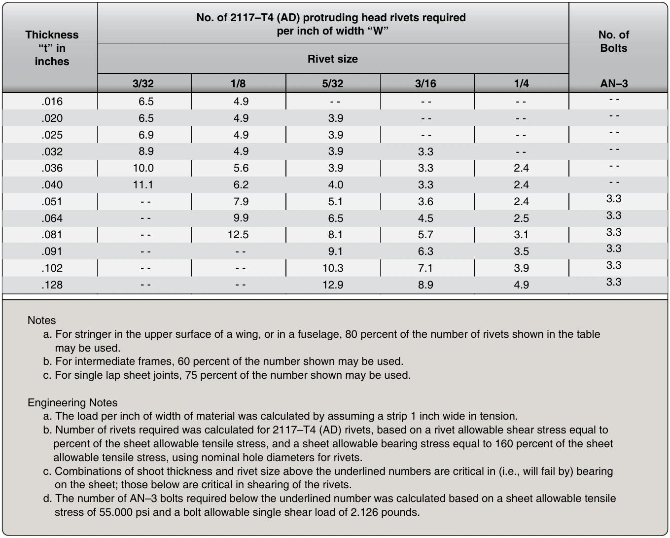
The size of rivets for any repair can be determined by referring to the rivets used by the manufacturer in the next parallel rivet row inboard on the wing or forward on the fuselage. Another method of determining the size of rivets to be used is to multiply the thickness of the skin by three and use the next larger size rivet corresponding to that figure. For example, if the skin thickness is 0.040-inch, multiply 0.040-inch by 3, which equals 0.120-inch; use the next larger size rivet, 1⁄8-inch (0.125-inch). The number of rivets to be used for a repair can be found in tables in manufacturer’s SRMs or in Advisory Circular (AC) 43.13-1 (as revised), Acceptable Methods, Techniques, and Practices—Aircraft Inspection and Repair. Figure 4-169 is a table from AC 43.13-1 that is used to calculate the number of rivets required for a repair.
Extensive repairs that are made too strong can be as undesirable as repairs weaker than the original structure. All aircraft structure must flex slightly to withstand the forces imposed during takeoff, flight, and landing. If a repaired area is too strong, excessive flexing occurs at the edge of the completed repair, causing acceleration of metal fatigue.
Shear Strength & Bearing Strength
Aircraft structural joint design involves an attempt to find the optimum strength relationship between being critical in shear and critical in bearing. These are determined by the failure mode affecting the joint. The joint is critical in shear if less than the optimum number of fasteners of a given size are installed. This means that the rivets will fail, and not the sheet, if the joint fails. The joint is critical in bearing if more than the optimum number of fasteners of a given size are installed; the material may crack and tear between holes, or fastener holes may distort and stretch while the fasteners remain intact.
Maintaining Original Contour
Form all repairs in such a manner to fit the original contour perfectly. A smooth contour is especially desirable when making patches on the smooth external skin of high-speed aircraft.
Keeping Weight to a Minimum
Keep the weight of all repairs to a minimum. Make the size of the patches as small as practicable and use no more rivets than are necessary. In many cases, repairs disturb the original balance of the structure. The addition of excessive weight in each repair may unbalance the aircraft, requiring adjustment of the trim-and-balance tabs. In areas such as the spinner on the propeller, a repair requires application of balancing patches in order to maintain a perfect balance of the propeller.
When flight controls are repaired and weight is added, it is very important to perform a balancing check to determine if the flight control is still within its balance limitations. Failure to do so could result in flight control flutter.
Flutter & Vibration Precautions
To prevent severe vibration or flutter of flight control surfaces during flight, precautions must be taken to stay within the design balance limitations when performing maintenance or repair. The importance of retaining the proper balance and rigidity of aircraft control surfaces cannot be overemphasized.