
Chapter 5
Aircraft Welding
Flux must be used in all silver soldering operations to ensure the base metal is chemically clean. The flux removes the film of oxide from the base metal and allows the silver solder to adhere to it.
All silver solder joints must be physically, as well as chemically, clean. The joint must be free of dirt, grease, oil, and/or paint. After removing the dirt, grease, etc., any oxide (rust and/or corrosion) should be removed by grinding or filing the piece until bright metal can be seen. During the soldering operation, the flux continues to keep the oxide away from the metal and aid in the flow of the solder.
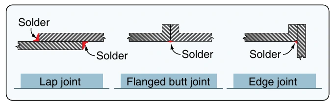
The three recommended types of joint for silver soldering are lap, flanged, and edge. With these, the metal is formed to furnish a seam wider than the base metal thickness and provide the type of joint that holds up under all types of loads. [Figure 5-27]
The oxy-acetylene flame for silver soldering should be a soft neutral or slightly reducing flame. That is, a flame with a slight excess of acetylene. During both preheating and application of the solder, the tip of the inner cone of the flame should be held about 1⁄2-inch from the work. The flame should be kept moving so that the metal does not overheat.
When both parts of the base metal are at the correct temperature, the flux flows and solder can be applied directly adjacent to the edge of the seam. It is necessary to simultaneously direct the flame over the seam and keep it moving so that the base metal remains at an even temperature.
Gas Tungsten Arc Welding (TIG Welding)
The TIG process as it is known today is a combination of the work done by General Electric in the 1920s to develop the basic process, the work done by Northrop in the 1940s to develop the torch itself, and the use of helium-shielding gas and a tungsten electrode. The process was developed for welding magnesium in the Northrop XP-56 flying wing to eliminate the corrosion and porosity issues with the atomic hydrogen process they had been using with a boron flux. It was not readily used on other materials until the late 1950s when it found merit in welding space-age super alloys. It was also later used on other metals, such as aluminum and steel, to a much greater degree.
Modern TIG welding machines are offered in DC, AC, or with AC/DC configurations, and use either transformer or inverter-based technology. Typically, a machine capable of AC output is required for aluminum. The TIG torch itself has changed little since the first Northrop patent. TIG welding is similar to oxy-fuel welding in that the heat source (torch) is manipulated with one hand, and the filler, if used, is manipulated with the other. A distinct difference is to control the heat input to the metal. The heat control may be preset and fixed by a machine setting or variable by use of a foot pedal or torch-mounted control.
Several types of tungsten electrode are used with the TIG welder. Thoriated and zirconiated electrodes have better electron emission characteristics than pure tungsten, making them more suitable for DC operations on transformer-based machines, or either AC or DC with the newer inverter-based machines. Pure tungsten provides a better current balance with AC welding with a transformer based machine, which is advantageous when welding aluminum and magnesium. The equipment manufacturers’ suggestions for tungsten type and form should be followed as this is an ever changing part of the TIG technology.
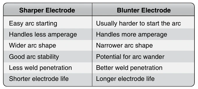
The shape of the electrode used in the TIG welding torch is an important factor in the quality and penetration of the weld. The tip of the electrode should be shaped on a dedicated grinding stone or a special-purpose tungsten grinder to avoid contaminating the electrode. The grinding should be done longitudinally, not radially, with the direction of stone travel away from the tip. Figure 5-28 shows the effects of a sharp versus blunt electrode with transformer-based machines.
When in doubt, consult the machine manufacturer for the latest up-to-date suggestions on tungsten preparation or if problems arise.
The general guidelines for weld quality, joint fit prior to welding, jigging, and controlling warp all apply to this process in the same regard as any other welding method. Of particular note are the additional process steps that sometimes must be taken to perform a quality weld; these are dealt within their appropriate sections.
TIG Welding 4130 Steel Tubing
Welding 4130 with TIG is not much different than welding other steels as far as technique is concerned. The following information generally addresses material under 0.120-inch thick.
Clean the steel of any oil or grease and use a stainless steel wire brush to clean the work piece prior to welding. This is to prevent porosity and hydrogen embrittlement during the welding process. The TIG process is highly susceptible to these problems, much more so than oxy-acetylene welding, so care must be taken to ensure all oils and paint are removed from all surfaces of the parts to be welded.
Use a TIG welder with high-frequency starting to eliminate arc strikes. Do not weld where there is any breeze or draft; the welds should be allowed to cool slowly. Preheating is not necessary for tubing of less than 0.120-inch wall thickness; however, post-weld tempering (stress relieving) is still recommended to prevent the possible brittleness of the area surrounding the weld due to the untempered martensite formations caused by the rapid cooling of the weld inherent to the TIG process.
If you use 4130 filler rod, preheat the work before welding and heat treat afterward to avoid cracking. In a critical situation such as this, engineering should be done to determine preheat and post-weld heat treatment needed for the particular application.
Weld at a slower speed, make sufficiently large fillets, and make them flat or slightly convex, not concave. After the welding is complete, allow the weldment to cool to room temperature. Using an oxy-acetylene torch set to a neutral flame, heat the entire weldment evenly to 1,100 °F–1,200 °F; hold this temperature for about 45 minutes per inch of metal thickness. The temperature is generally accepted to be a dull red in ambient lighting. Note that for most tubing sections, the temperature needs to be held for only a minute or two. This process is found in most materials engineering handbooks written by the Materials Information Society (ASM) and other engineering sources. When working on a critical component, seek engineering help if there is any doubt.