Chapter 5
Aircraft Welding
To form a uniform bead, the electrode must be moved along the plate at a constant speed in addition to the downward feed of the electrode. If the rate of advance is too slow, a wide overlapping bead forms with no fusion at the edges. If the rate is too fast, the bead is too narrow and has little or no fusion at the plate.
The proper length of the arc cannot be judged by looking at it. Instead, depend on the sound that the short arc makes. This is a sharp cracking sound, and it should be heard during the time the arc is being moved down to and along the surface of the plate.
A good weld bead on a flat plate should have the following characteristics:
- Little or no splatter on the surface of the plate.
- An arc crater in the bead of approximately 1⁄16-inch when the arc has been broken.
- The bead should be built up slightly, without metal overlap at the top surface.
- The bead should have a good penetration of approximately 1⁄16-inch into the base metal.
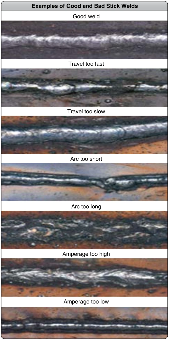
Figure 5-31 provides examples of operator’s technique and welding machine settings.
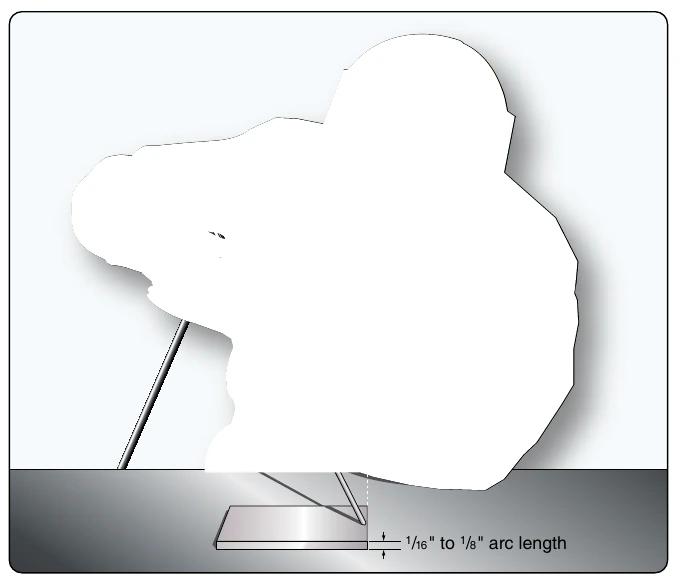
When advancing the electrode, it should be held at an angle of about 20° to 25° in the direction of travel moving away from the finished bead. [Figure 5-32]
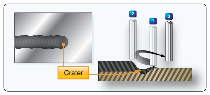
If the arc is broken during the welding of a bead and the electrode is removed quickly, a crater is formed at the point where the arc ends. This shows the depth of penetration or fusion that the weld is getting. The crater is formed by the pressure of the gases from the electrode tip forcing the weld metal toward the edges of the crater. If the electrode is removed slowly, the crater is filled.
If you need to restart an arc of an interrupted bead, start just ahead of the crater of the previous weld bead, as shown in position 1, Figure 5-33. Then, the electrode should be returned to the back edge of the crater (step 2). From this point, the weld may be continued by welding right through the crater and down the line of weld as originally planned (step 3).
Once a bead has been formed, every particle of slag must be removed from the area of the crater before restarting the arc. This is accomplished with a pick hammer and wire brush and prevents the slag from becoming trapped in the weld.
Multiple Pass Welding
Groove and fillet welds in heavy metals often require the deposit of a number of beads to complete a weld. It is important that the beads be deposited in a predetermined sequence to produce the soundest welds with the best proportions. The number of beads is determined by the thickness of the metal being welded.
Plates from 1⁄8-inch to ¼-inch can be welded in one pass, but they should be tacked at intervals to keep them aligned. Any weld on a plate thicker than ¼-inch should have the edges beveled and multiple passes.
The sequence of the bead deposits is determined by the kind of joint and the position of the metal. All slag must be removed from each bead before another bead is deposited. Typical multiple-pass groove welding of butt joints is shown in Figure 5-34.
Techniques of Position Welding
Each time the position of a welded joint or the type of joint is changed, it may be necessary to change any one or a combination of the following:
- Current value
- Electrode
- Polarity
- Arc length
- Welding technique
Current values are determined by the electrode size, as well as the welding position. Electrode size is governed by the thickness of the metal and the joint preparation. The electrode type is determined by the welding position. Manufacturers specify the polarity to be used with each electrode. Arc length is controlled by a combination of the electrode size, welding position, and welding current.