Chapter 6
Aircraft Wood & Structural Repair
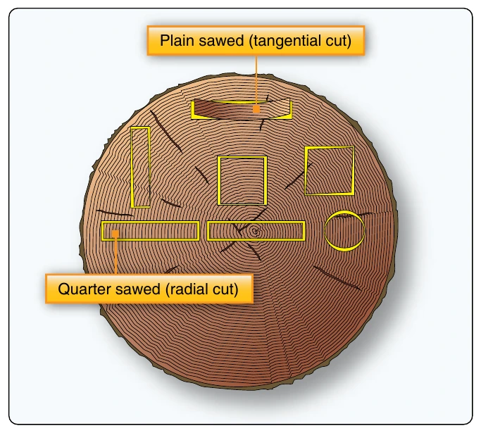
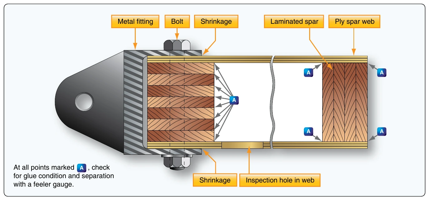
Inspect the glue line using a magnifying glass. Where the glue line tends to part, or where the presence of glue cannot be detected or is suspect, probe the glue line with a thin feeler gauge. If any penetration is observed, the joint is defective. The structure usually dictates the feeler gauge thickness, but use the thinnest feeler gauge whenever possible. The illustration indicates the points a feeler gauge should probe. [Figure 6-6]
Pressure exerted on a joint either by the surrounding structure or by metal attachment devices, such as bolts or screws, can cause a false appearance of the glue condition. The joint must be relieved of this pressure before the glue line inspection is performed.
A glued joint may fail in service as a result of an accident or because of excessive mechanical loads having been imposed upon it. Glued joints are generally designed to take shear loads. If a joint is expected to take tension loads, it is secured by a number of bolts or screws in the area of tension loading. In all cases of glued joint failure, whatever the direction of loading, there should be a fine layer of wood fibers adhering to the glue. The presence of fibers usually indicates that the joint itself is not at fault.
Examination of the glue under magnification that does not reveal any wood fibers, but shows an imprint of the wood grain, indicates that the cause of the failure was the predrying of the glue before applying pressure during the manufacture of the joint. If the glue exhibits an irregular appearance with star-shaped patterns, this is an indication that precuring of the glue occurred before pressure was applied, or that pressure had been incorrectly applied or maintained on the joint. If there is no evidence of wood fiber adhesion, there may also be glue deterioration.
Wood Condition
Wood decay and dry rot are usually easy to detect. Decay may be evident as either a discoloration or a softening of the wood. Dry rot is a term loosely applied to many types of decay, but especially to a condition that, in an advanced stage, permits the wood to be crushed to a dry powder. The term is actually a misnomer for any decay, since all fungi require considerable moisture for growth.
Dark discolorations of the wood or gray stains running along the grain are indicative of water penetration. If such discoloration cannot be removed by light scraping, replace the part. Disregard local staining of the wood by dye from a synthetic adhesive hardener.
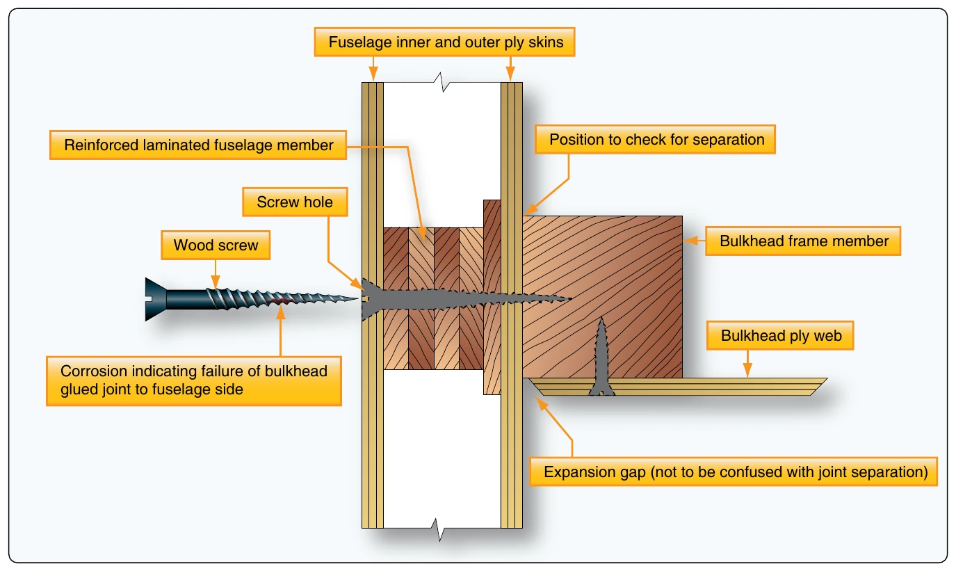
In some instances where water penetration is suspected, a few screws removed from the area in question reveal, by their degree of corrosion, the condition of the surrounding joint. [Figure 6-7]
Another method of detecting water penetration is to remove the bolts holding the fittings at spar root-end joints, aileron hinge brackets, etc. Corrosion on the surface of such bolts and wood discoloration provide a useful indication of water penetration.
Plain brass screws are normally used for reinforcing glued wooden members. For hardwoods, such as mahogany or ash, steel screws may be used. Unless specified by the aircraft manufacturer, replace removed screws with new screws of identical length, but one gauge larger in diameter.
Inspection experience with a particular type of aircraft provides insight to the specific areas most prone to water penetration and moisture entrapment. Wooden aircraft are more prone to the damaging effects of water, especially without the protection of covered storage. Control system openings, fastener holes, cracks or breaks in the finish, and the interfaces of metal fittings and the wood structure are points that require additional attention during an inspection. Additionally, windshield and window frames, the area under the bottom of entrance and cargo doors, and the lower sections of the wing and fuselage are locations that require detailed inspections for water damage and corrosion on all aircraft.
The condition of the fabric covering on plywood surfaces provides an indication of the condition of the wood underneath. If there is any evidence of poor adhesion, cracks in the fabric, or swelling of the wood, remove the fabric to allow further inspection. The exposed surface shows water penetration by the existence of dark gray streaks along the grain and dark discoloration at ply joints or screw holes.
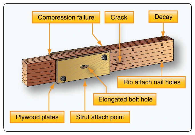
Cracks in wood spars are often hidden under metal fittings or metal rib flanges and leading edge skins. Any time a Check all metal fittings that are attached to a wood structure for looseness, corrosion, cracks, or bending. Areas of particular concern are strut attach fittings, spar butt fittings, aileron and flap hinges, jury strut fittings, compression struts, control cable pulley brackets, and landing gear fittings. All exposed end grain wood, particularly the spar butts, should be inspected for cracking or checking.
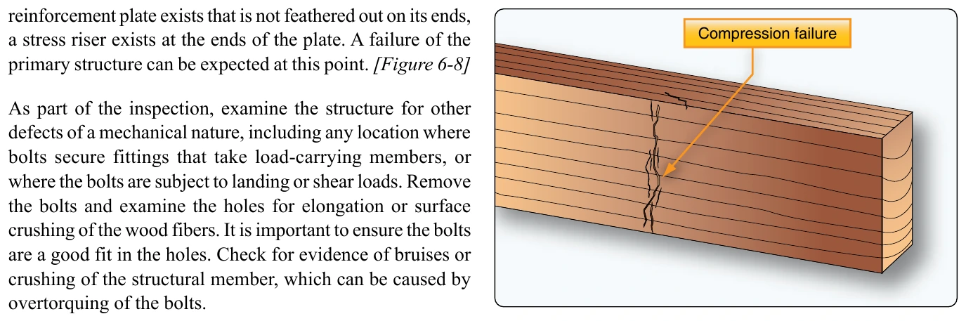
Inspect structural members for compression failures, which is indicated by rupture across the wood fibers. This is a serious defect that can be difficult to detect. If a compression failure is suspected, a flashlight beam shown along the member and running parallel to the grain, will assist in revealing it. The surface will appear to have minute ridges or lines running across the grain. Particular attention is necessary when inspecting any wooden member that has been subjected to abnormal bending or compression loads during a hard landing. If undetected, compression failures of the spar may result in structural failure of the wing during flight. [Figure 6-9]
When a member has been subjected to an excessive bending load, the failure appears on the surface that has been compressed. The surface subject to tension normally shows no defects. In the case of a member taking an excessive direct compression load, the failure is apparent on all surfaces.