
Chapter 6
Aircraft Wood & Structural Repair
Satisfactory glue joints in aircraft should develop the full strength of the wood under all conditions of stress. Tests should be made by the mechanic prior to gluing a joint of a major repair, such as a wing spar. Whenever possible, perform tests using pieces cut from the actual wood used for the repair under the same mechanical and environmental conditions that the repair will undergo.
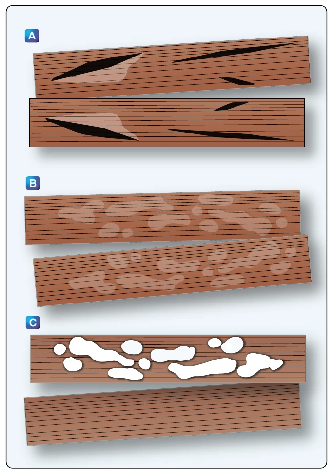
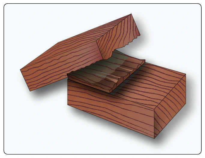
Perform a sample test using two pieces of scrap wood from the intended repair, each cut approximately 1" × 2" × 4". The pieces should be joined by overlapping each approximately 2 inches. The type of glue, pressure, and curing time should be the same as used for the actual repair. After full cure, place the test sample in a bench vise and break the joint by exerting pressure on the overlapping member. The fractured glue faces should show a high percentage of at least 75 percent of the wood fibers evenly distributed over the fractured glue surface. [Figure 6-14]
Repair of Wood Aircraft Components
Wing Rib Repairs
Ribs that have sustained damage may be repaired or replaced, depending upon the type of damage and location in the aircraft. If new parts are available from the aircraft manufacturer or the holder of a PMA for the part, it is advisable to replace the part rather than to repair it.
If you make a repair to a rib, do the work in such a manner and using materials of such quality that the completed repair is at least equal to the original part in aerodynamic function, structural strength, deterioration, and other qualities affecting airworthiness, such as fit and finish. When manufacturer’s repair manuals or instructions are not available, acceptable methods of repairing damaged ribs are described in AC 43.13-1 under Wood Structure Repairs.
When necessary, a rib can be fabricated and installed using the same materials and dimensions from a manufacturer-approved drawing or by reference to an original rib. However, if you fabricated it from an existing rib, you must provide evidence to verify that the dimensions are accurate and the materials are correct for the replacement part.
You can repair a cap strip of a wood rib using a scarf splice. The repair is reinforced on the side opposite the wing covering by a spruce block that extends beyond the scarf joint not less than three times the thickness of the strips being repaired. Reinforce the entire splice, including the spruce reinforcing block, on each side with a plywood side plate.
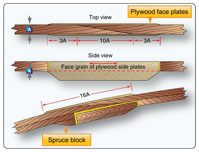
The scarf length bevel is 10 times dimension A (thickness of the rib cap strip) with the spruce reinforcement block being 16 times dimension A (the scarf length plus extension on either end of the scarf). The plywood splice plates should be of the same material and thickness as the original plates used to fabricate the rib. The spruce block should have a 5:1 bevel on each end. [Figure 6-15]
These specific rib repairs describing the use of one scarf splice implies that either the entire forward or aft portion of the cap strip beyond the damage can be replaced to complete the repair and replace the damaged section. Otherwise, replacement of the damaged section may require a splice repair at both ends of the replaced section of the cap strip using the indicated dimensions for cutting and reinforcing of each splice.
When a cap strip is to be repaired at a point where there is a joint between it and cross members of the rib, make the repair by reinforcing the scarf joint with plywood gussets, as shown in Figure 6-16.
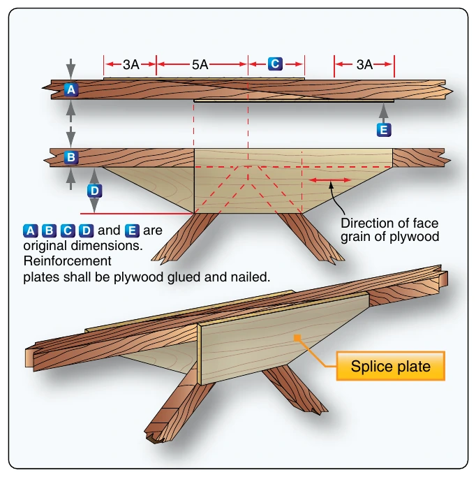
If a cap strip must be repaired where it crosses a spar, reinforce the joint with a continuous gusset extending over the spar, as shown in Figure 6-17.
The scarf joints referred to in the rib repairs are the most satisfactory method of fabricating an end joint between two solid wood members. When the scarf splice is used to repair a solid wood component, the mechanic must be aware of the direction and slope of the grain. To ensure the full strength of the joint, the scarf cut is made in the general direction of the grain on both connecting ends of the wood and then correctly oriented to each other when glued. [Figure 6-18]
The trailing edge of a rib can be replaced and repaired by removing the damaged portion of the cap strip and inserting a softwood block of white pine, spruce, or basswood. The entire repair is then reinforced with plywood gussets and nailed and glued, as shown in Figure 6-19.
Compression ribs are of many different designs, and the proper method of repairing any part of this type of rib is specified by the manufacturer. All repairs should be performed using recommended or approved practices, materials, and adhesives.
Figure 6-20A illustrates the repair of a compression rib of the I section type (i.e., wide, shallow cap strips, and a center plywood web with a rectangular compression member on each side of the web). The rib damage suggests that the upper and lower cap strips, the web member, and the compression members are cracked completely through. To facilitate this repair, cut the compression members as shown in Figure 6-20D and repair as recommended using replacement sections to the rear spar. Cut the damaged cap strips and repair as shown in Figure 6-20, replacing the aft section of the cap strips. Plywood side plates are then bonded on each side diagonally to reinforce the damaged web as shown in Figure 6-20, A-A.