
Chapter 6
Aircraft Wood & Structural Repair
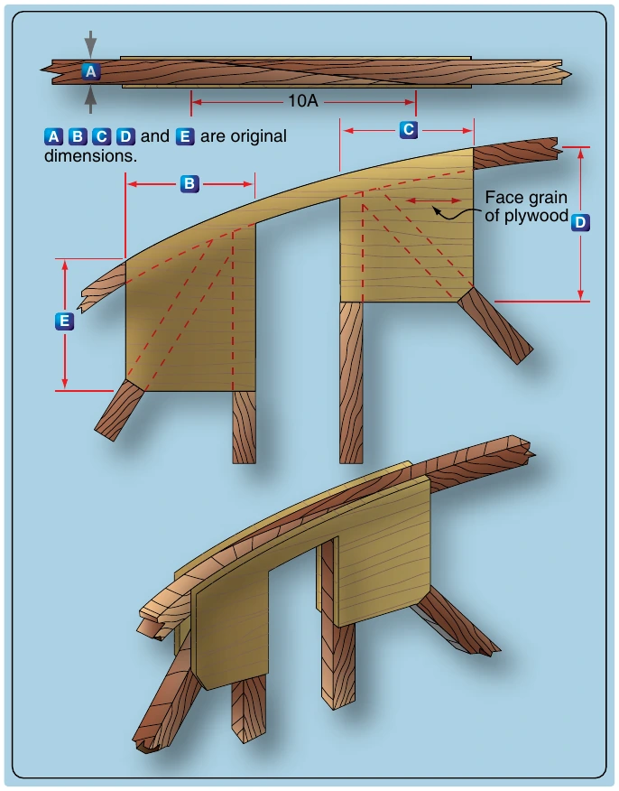
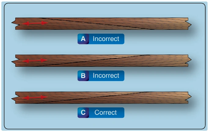
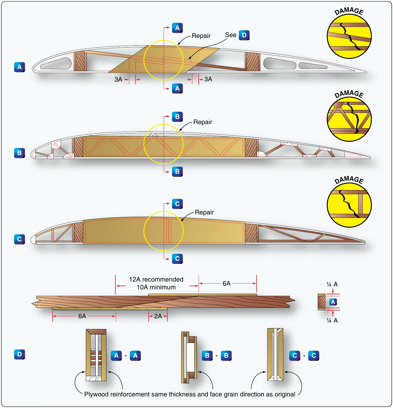
Figure 6-20B illustrates a compression rib of the type that is a standard rib with rectangle compression members added to one side and a plywood web to the other side. The method used in this repair is essentially the same as in Figure 6-20A, except that the plywood reinforcement plate, shown in Figure 6-20B-B, is continued the full distance between the spars.
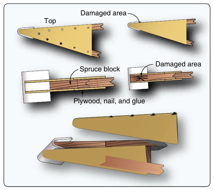
Figure 6-20C illustrates a compression rib of the I type with a rectangular vertical member on each side of the web. The method of repair is essentially the same as in Figure 6-20A, except the plywood reinforcement plates on each side, shown in Figure 6-20C-C, are continued the full distance between the spars.
Wing Spar Repairs
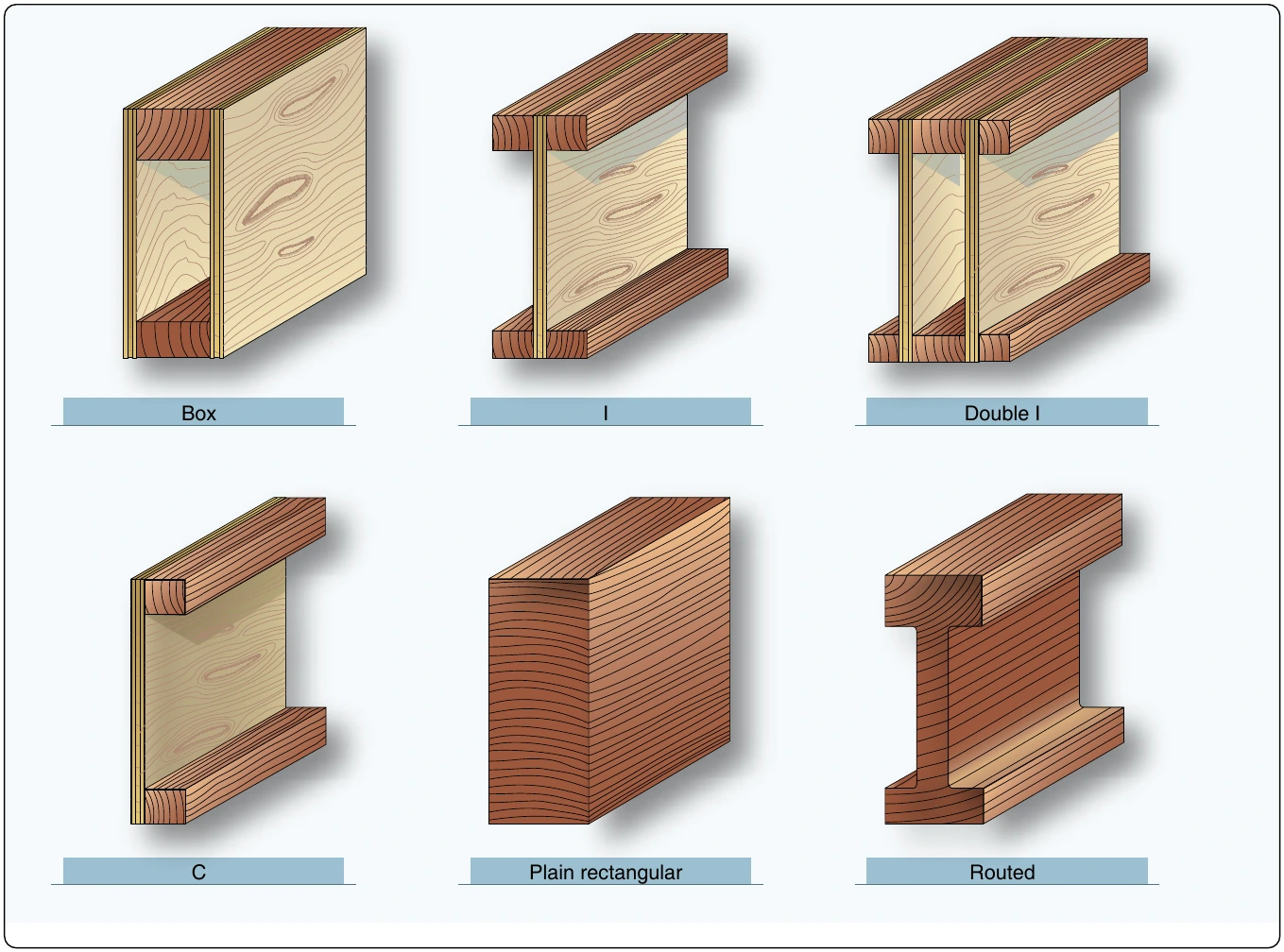
Wood wing spars are fabricated in various designs using solid wood, plywood, or a combination of the two. [Figure 6-21]
When a spar is damaged, the method of repair must conform to the manufacturer’s instructions and recommendations. In the absence of manufacturer’s instructions, contact the FAA for advice and approval before making repairs to the spar and following recommendations in AC 43.13-1. If instructions are not available for a specific type of repair, it is highly recommended that you request appropriate engineering assistance to evaluate and provide guidance for the intended repair.
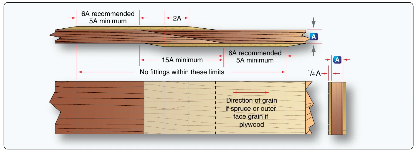
Shown in Figure 6-22 is a recommended method to repair either a solid or laminated rectangle spar. The slope of the scarf in any stressed part, such as a spar, should not be steeper than 15 to 1.
Unless otherwise specified by the aircraft manufacturer, a damaged spar may be spliced at almost any point except at wing attachment fittings, landing gear fittings, engine mount fittings, or lift-and-interplane strut fittings. These fittings may not overlap any part of the splice. The reinforcement plates of the splice should not interfere with the proper attachment or alignment of the fittings. Taper reinforcement plates on the ends at a 5:1 slope [Figure 6-23].
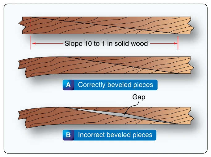
The use of a scarf joint to repair a spar or any other component of an aircraft is dependent on the accessibility to the damaged section. It may not be possible to utilize a scarf repair where recommended, so the component may have to be replaced. A scarf must be precisely cut on both adjoining pieces to ensure an even thin glue line; otherwise, the joint may not achieve full strength. The primary difficulty encountered in making this type of joint is obtaining the same bevel on each piece. [Figure 6-24]
The mating surfaces of the scarf must be smooth. You can machine smooth a saw cut using any of a variety of tools, such as a plane, a joiner, or a router. For most joints, you need a beveled fixture set at the correct slope to complete the cut. Figure 6-25 illustrates one method of producing an accurate scarf joint.
Once the two bevels are cut for the intended splice, clamp the pieces to a flat guide board of similar material. Then, work a sharp, fine-tooth saw all the way through the joint. Remove the saw, decrease pressure, and tap one of the pieces on the end to close the gap. Work the saw again through the joint. Continue this procedure until the joint is perfectly parallel with matching surfaces. Then, make a light cut with the grain, using a sharp plane, to smooth both mating surfaces.
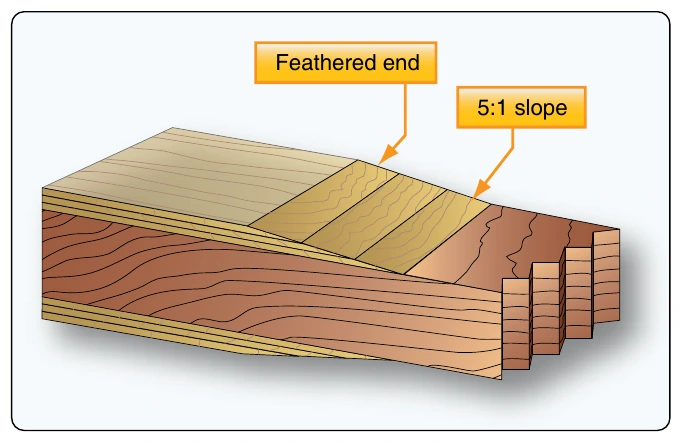
Another method of cutting a scarf uses a simple scarf-cutting fixture that you can also fabricate for use with a router. Extend the work piece beyond the edge so the finished cut results in a feathered edge across the end of the scarf. [Figure 6-26] There are numerous tools made by individuals, and there are commercial plans for sale with instructions for building scarf-cutting tools. Most of them work, but some are better than others. The most important requirement for the tool is that it produces a smooth, repeatable cut at the appropriate angle.
Local damage to the top or bottom edge of a solid spar may be repaired by removing the damaged portion and fabricating a replacement filler block of the same material as the spar. Full width doublers are fabricated as shown and then all three pieces are glued and clamped to the spar. Nails or screws should not be used in spar repairs. A longitudinal crack in a solid spar may be repaired using doublers made from the proper thickness plywood. Care must be taken to ensure the doublers extend the minimum distance beyond the crack.