
Chapter 7
Advanced Composite Materials
Honeycomb sandwich parts often have thin face sheets and are most effectively repaired by using a bonded scarf type repair. A bonded external step patch can be used as an alternative. Bolted repairs are not effective for thin laminates because of the low bearing stress of the composite laminate. Thicker solid laminates used on larger aircraft can be up to an inch thick in highly loaded areas and these types of laminates cannot be effectively repaired using a bonded scarf type repair. [Figure 7-74]
Bolted Repairs
Aircraft designed in the 1970s used composite sandwich honeycomb structure for lightly loaded secondary structure, but new large aircraft use thick solid laminates for primary structure instead of sandwich honeycomb. These thick solid laminate structures are quite different from the traditional sandwich honeycomb structures used for flight controls, landing gear doors, flaps, and spoilers of today’s aircraft. They present a challenge to repair and are difficult to repair with a bonded repair method. Bolted repair methods have been developed to repair thicker solid laminates.
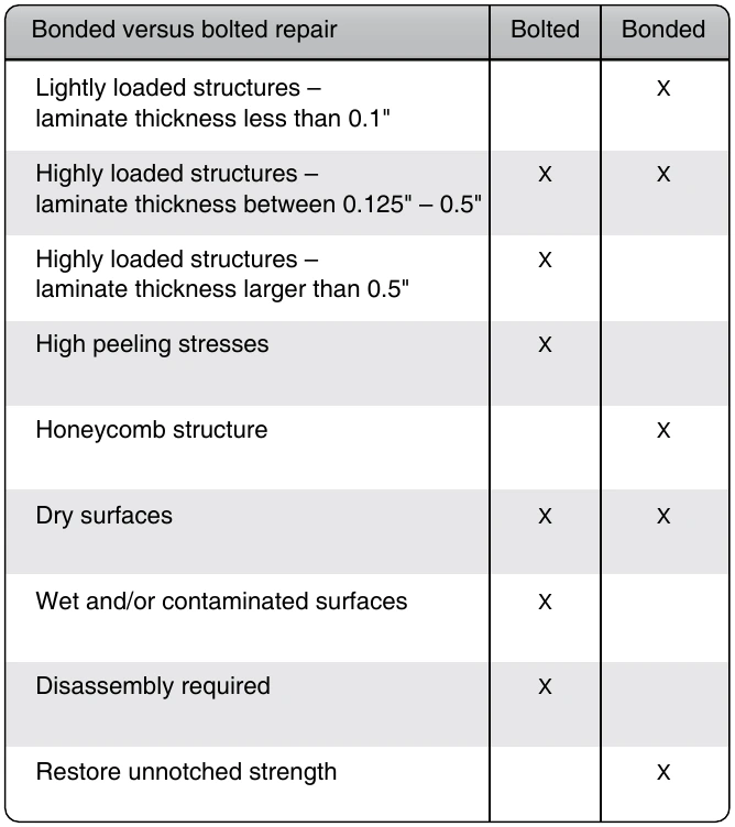
Bolted repairs are not desirable for honeycomb sandwich structure due to the limited bearing strength of the thin face sheets and weakened honeycomb structure from drilling holes. The advantage of a bolted repair is that you need to select only patch material and fasteners, and the repair method is similar to a sheet metal repair. There is no need for curing the repair and storing the prepreg repair material and film adhesives in a freezer. Patches may be made from aluminum, titanium, steel, or precured composite material. Composite patches are often made from carbon fiber with an epoxy resin or fiberglass with an epoxy resin.
You can repair a carbon fiber structure with an aluminum patch, but you must place a layer of fiberglass cloth between the carbon part and the aluminum patch to prevent galvanic corrosion. Titanium and precured composite patches are preferred for repair of highly loaded components. Precured carbon/epoxy patches have the same strength and stiffness as the parent material as they are usually cured similarly.
Titanium or stainless steel fasteners are used for bolted repairs of a carbon fiber structure. Aluminum fasteners corrode if used with carbon fiber. Rivets cannot be used because the installation of rivets using a rivet gun introduce damage to the hole and surrounding structure and rivets expand during installation, which is undesirable for composite structures because it could cause delimination of the composite material.
Repair Procedures Step 1: Inspection of the Damage
The tap test is not effective to detect delamination in thick laminates unless the damage is close to the surface. An ultrasonic inspection is necessary to determine the damage area. Consult the SRM to find an applicable NDI procedure.
Step 2: Removal of the Damage
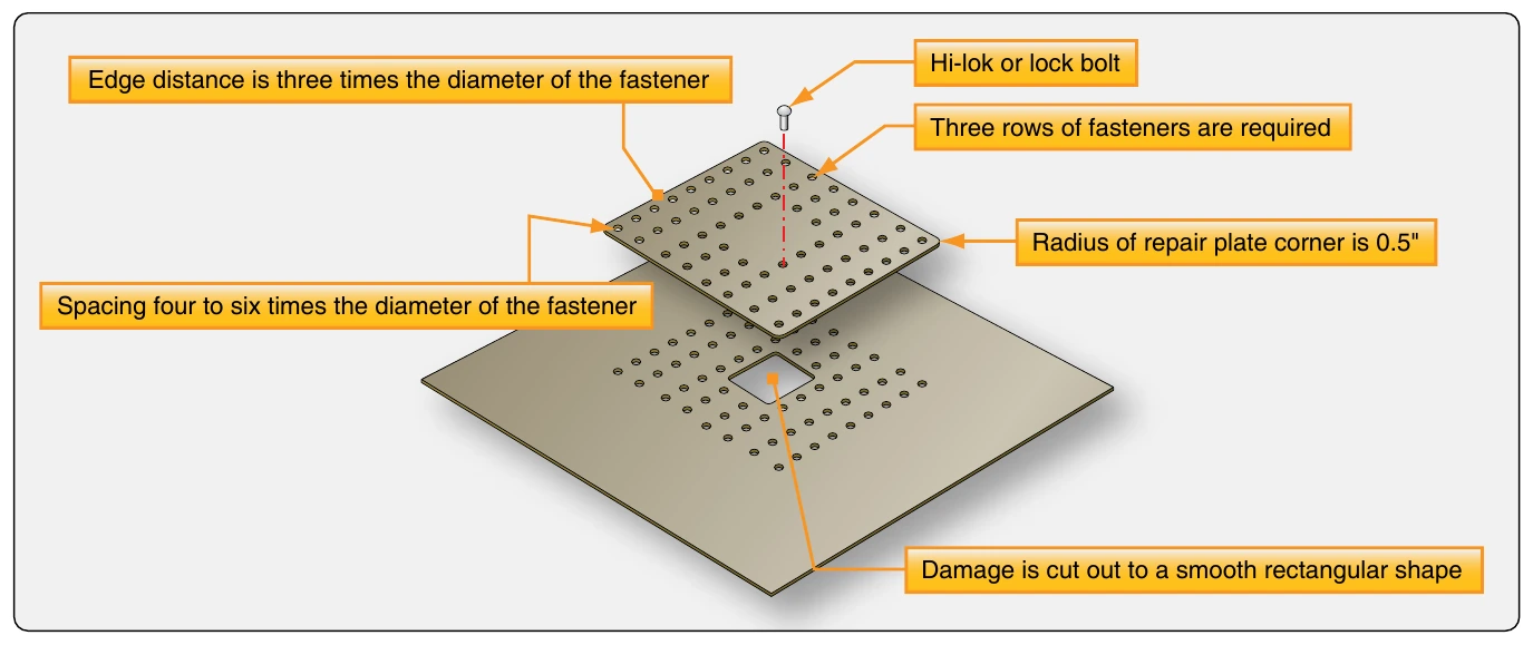
The damaged area needs to be trimmed to a round or rectangular hole with large smooth radii to prevent stress concentrations. Remove the damage with a sander, router, or similar tool.
Step 3: Patch Preparation
Determine the size of the patch based on repair information found in the SRM. Cut, form, and shape the patch before attaching the patch to the damaged structure. It is easier to make the patch a little bigger than calculated and trim to size after drilling all fastener holes. In some cases, the repair patches are stocked preshaped and predrilled. If cutting is to be performed, standard shop procedures should be used that are suitable for the patch material. Titanium is hard to work and requires a large powerful slip roller to curve the material. Metal patches require filing to prevent crack initiation around the cut edges. When drilling pilot holes in the composite, the holes for repair fasteners must be a minimum of four diameters from existing fasteners and have a minimum edge distance of three fastener diameters. This is different from the standard practice for aluminum of allowing a two diameter distance. Specific pilot hole sizes and drill types to be used should follow specific SRM instructions. [Figure 7-75]
Step 4: Hole Pattern Lay Out
To locate the patch on the damaged area, draw two perpendicular centerlines on the parent structure and on the patch material that define the principal load or geometric directions. Then, lay out hole pattern on the patch and drill pilot holes in the patch material. Align the two perpendicular centerlines of the patch with the lines on the parent structure and transfer the pilot holes to the parent material. Use clecos to keep the patch in place. Mark the edges of the patch so that it can be returned to the same location easily.
Step 5: Drilling & Reaming Holes in Patch & Parent Structure
Composite skins should be backed up to prevent splitting. Enlarge the pilot holes in the patch and parent materials with a drill 1⁄64 undersize and then ream all holes to the correct size. A tolerance of +0.0025/–0.000-inch is usually recommended for aircraft parts. For composites, this means interference fasteners are not used.
Step 6: Fastener Installation
Once fastener holes are drilled full size and reamed, permanent fasteners are installed. Before installation, measure the fastener grip length for each fastener using a grip length gauge. As different fasteners are required for different repairs, consult the SRM for permissible fastener type and installation procedure. However, install all fasteners wet with sealant and with proper torque for screws and bolts.