
Chapter 7
Advanced Composite Materials
Drilling
Hole drilling in composite materials is different from drilling holes in metal aircraft structures. Different types of drill bits, higher speeds, and lower feeds are required to drill precision holes. Structures made from carbon fiber and epoxy resin are very hard and abrasive, requiring special flat flute drills or similar four-flute drills. Aramid fiber (Kevlar®)/epoxy composites are not as hard as carbon but are difficult to drill unless special cutters are used because the fibers tend to fray or shred unless they are cut clean while embedded in the epoxy. Special drill bits with clothes pin points and fish-tail points have been developed that slice the fibers prior to pulling them out of the drilled hole. If the Kevlar®/epoxy part is sandwiched between two metal parts, standard twist drills can be used.
Equipment
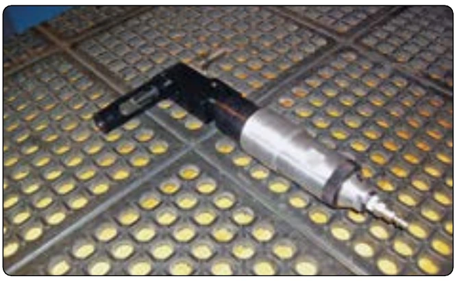
Air-driven tools are used for drilling holes in composite materials. Drill motors with free speed of up to 20,000 rpm are used. A general rule for drilling composites is to use high speed and a low feed rate (pressure). Drilling equipment with a power feed control produces better hole quality than drill motors without power feed control. Drill guides are recommended, especially for thicker laminates.
Do not use standard twist drill bits for drilling composite structures. Standard high-speed steel is unacceptable, because it dulls immediately, generates excessive heat, and causes ply delamination, fiber tear-out, and unacceptable hole quality.
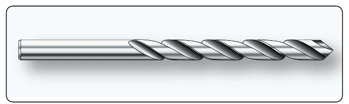
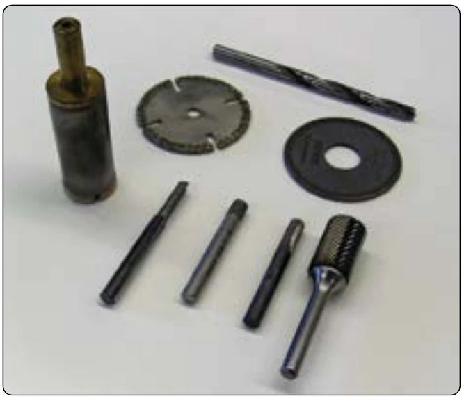
Drill bits used for carbon fiber and fiberglass are made from diamond-coated material or solid carbide because the fibers are so hard that standard high-speed steel (HSS) drill bits do not last long. Typically, twist drills are used, but brad point drills are also available. The Kevlar® fibers are not as hard as carbon, and standard HSS drill bits can be used. The hole quality can be poor if standard drill bits are used and the preferred drill style is the sickle-shaped Klenk drill. This drill first pulls on the fibers and then shears them, which results in a better quality hole. Larger holes can be cut with diamond-coated hole saws or fly cutters, but only use fly cutters in a drill press, and not in a drill motor. [Figures 7-85, 7-86, and 7-87]
Processes & Precautions
Composite materials are drilled with drill motors operating between 2,000 and 20,000 rpm and a low feed rate. Drill motors with a hydraulic dash pod or other type of feed control are preferred because they restrict the surging of the drill as it exits the composite materials. This reduces breakout damage and delaminations. Parts made from tape products are especially susceptible to breakout damage; parts made from fabric material have experienced less damage. The composite structure needs to be backed with a metal plate or sheet to avoid breakout. Holes in composite structures are often predrilled with a small pilot hole, enlarged with a diamond-coated or carbide drill bit and reamed with a carbide reamer to final hole size.
Back counterboring is a condition that can occur when carbon/epoxy parts mate metal substructure parts. The back edge of the hole in the carbon/epoxy part can be eroded or radiused by metal chips being pulled through the composite. The condition is more prevalent when there are gaps between the parts or when the metal debris is stringy rather than small chips. Back counterboring can be minimized or eliminated by changing feeds and speeds, cutter geometry, better part clamp-up adding a final ream pass, using a peck drill, or combination of these.
When drilling combinations of composite parts with metal parts, the metal parts may govern the drilling speed. For example, even though titanium is compatible with carbon/epoxy material from a corrosion perspective, lower drilling speeds are required in order to ensure no metallurgical damage occurs to the titanium. Titanium is drilled with low speed and high feed. Drill bits suitable for titanium might not be suitable for carbon or fiberglass. Drill bits that are used for drilling titanium are often made from cobalt-vanadium; drill bits used for carbon fiber are made from carbide or are diamond coated to increase drill life and to produce an accurate hole. Small-diameter high-speed steel drill bits, such as No. 40 drill, which are used to manually drill pilot holes, are typically used because carbide drills are relatively brittle and are easily broken. The relatively low cost of these small HSS drill bits offsets the limited life expectancy. High-speed steel drill bits may last for only one hole.
The most common problem with carbide cutters used in hand-drill operations is handling damage (chipped edges) to the cutters. A sharp drill with a slow constant feed can produce a 0.1 mm (0.004-inch) tolerance hole through carbon/epoxy plus thin aluminum, especially if a drill guide is used. With hard tooling, tighter tolerances can be maintained. When the structure under the carbon/epoxy is titanium, drills can pull titanium chips through the carbon/epoxy and enlarge the hole. In this case, a final ream operation may be required to hold tight hole tolerances. Carbide reamers are needed for holes through carbon/epoxy composite structure. In addition, the exit end of the hole needs good support to prevent splintering and delaminations when the reamer removes more than about 0.13 mm (0.005-inch) on the diameter. The support can be the substructure or a board held firmly against the back surface. Typical reaming speeds are about one-half of the drilling speed.
Cutting fluids are not normally used or recommended for drilling thin (less than 6.3 mm, or 0.25-inch thick) carbon/epoxy structures. It is good practice to use a vacuum while drilling into composite materials to prevent carbon dust from freely floating around the work area.
Countersinking
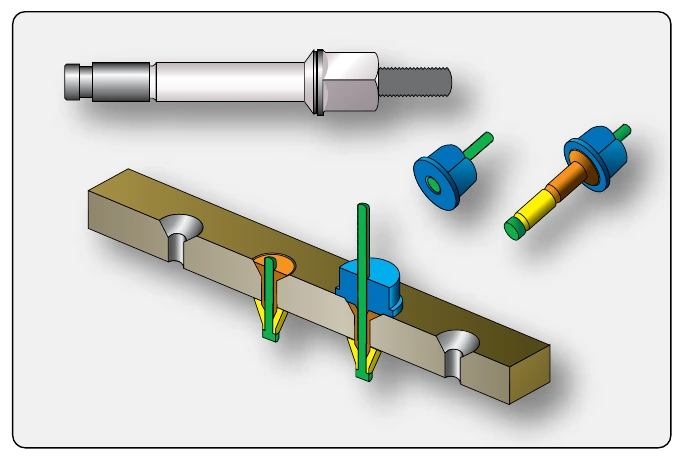
Countersinking a composite structure is required when flush head fasteners are to be installed in the assembly. For metallic structures, a 100° included angle shear or tension head fastener has been the typical approach. In composite structures, two types of fasteners are commonly used: a 100° included angle tension head fastener or a 130° included angle head fastener. The advantage of the 130° head is that the fastener head can have about the same diameter as a tension head 100° fastener with the head depth of a shear-type head 100° fastener. For seating flush fasteners in composite parts, it is recommended that the countersink cutters be designed to produce a controlled radius between the hole and the countersink to accommodate the head-to-shank fillet radius on the fasteners. In addition, a chamfer operation or a washer may be required to provide proper clearance for protruding head fastener head-to-shank radii. Whichever head style is used, a matching countersink/chamfer must be prepared in the composite structure.
Carbide cutters are used for producing a countersink in carbon/epoxy structure. These countersink cutters usually have straight flutes similar to those used on metals. For Kevlar® fiber/epoxy composites, S-shaped positive rake cutting flutes are used. If straight-fluted countersink cutters are used, a special thick tape can be applied to the surface to allow for a clean cutting of the Kevlar® fibers, but this is not as effective as the S-shaped fluted cutters. Use of a piloted countersink cutter is recommended because it ensures better concentricity between the hole and the countersink and decreases the possibility of gaps under the fasteners due to misalignment or delaminations of the part.
Use a microstop countersink gauge to produce consistent countersink wells. Do not countersink through more than 70 percent of the skin depth because a deeper countersink well reduces material strength. When a piloted countersink cutter is used, the pilot must be periodically checked for wear, as wear can cause reduction of concentricity between the hole and countersink. This is especially true for countersink cutters with only one cutting edge. For piloted countersink cutters, position the pilot in the hole and bring the cutter to full rpm before beginning to feed the cutter into the hole and preparing the countersink. If the cutter is in contact with the composite before triggering the drill motor, you may get splintering.