
Chapter 9
Aircraft Electrical System
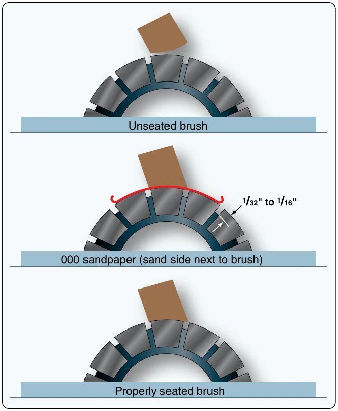
Pull the sandpaper in the direction of armature rotation, being careful to keep the ends of the sandpaper as close to the slip ring or commutator surface as possible in order to avoid rounding the edges of the brush. When pulling the sandpaper back to the starting point, raise the brush so it does not ride on the sandpaper. Sand the brush only in the direction of rotation. Carbon dust resulting from brush sanding should be thoroughly cleaned from all parts of the generators after a sanding operation.
After the generator has run for a short period, brushes should be inspected to make sure that pieces of sand have not become embedded in the brush. Under no circumstances should emery cloth or similar abrasives be used for seating brushes (or smoothing commutators), since they contain conductive materials that cause arcing between brushes and commutator bars. It is important that the brush spring pressure be correct. Excessive pressure causes rapid wear of brushes. Too little pressure, however, allows bouncing of the brushes, resulting in burned and pitted surfaces. The pressure recommended by the manufacturer should be checked by the use of a spring scale graduated in ounces. Brush spring tension on some generators can be adjusted. A spring scale is used to measure the pressure that a brush exerts on the commutator.
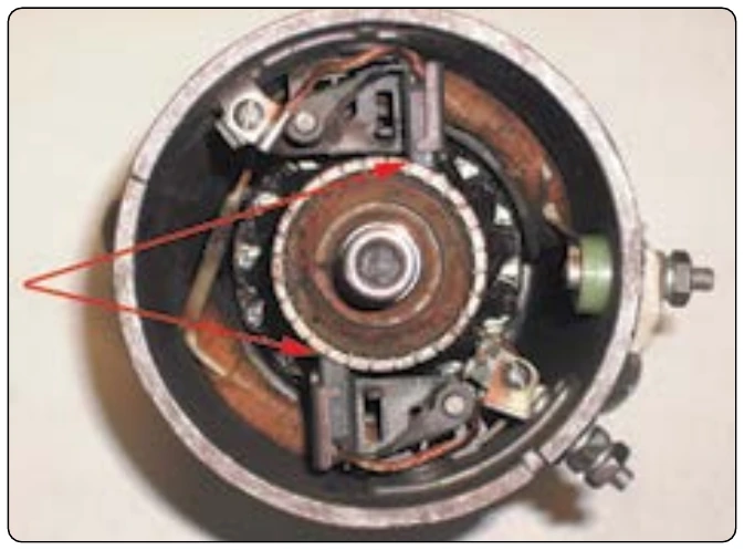
Flexible low-resistance pigtails are provided on most heavy current carrying brushes, and their connections should be securely made and checked at frequent intervals. The pigtails should never be permitted to alter or restrict the free motion of the brush. The purpose of the pigtail is to conduct the current from the armature, through the brushes, to the external circuit of the generator.
Generator Controls
Theory of Generator Control
All aircraft are designed to operate within a specific voltage range (for example 13.5–14.5 volts). And since aircraft operate at a variety of engine speeds (remember, the engine drives the generator) and with a variety of electrical demands, all generators must be regulated by some control system. The generator control system is designed to keep the generator output within limits for all flight variables. Generator control systems are often referred to as voltage regulators or generator control units (GCU).
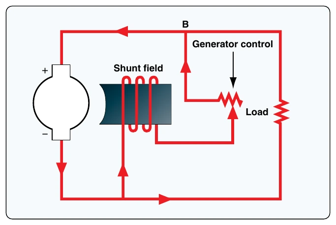
Aircraft generator output can easily be adjusted through control of the generator’s magnetic field strength. Remember, the strength of the magnetic field has a direct effect on generator output. More field current means more generator output and vice versa. Figure 9-54 shows a simple generator control used to adjust field current. When field current is controlled, generator output is controlled. Keep in mind, this system is manually adjusted and would not be suitable for aircraft. Aircraft systems must be automatic and are therefore a bit more complex.
There are two basic types of generator controls: electromechanical and solid-state (transistorized). The electromechanical type controls are found on older aircraft and tend to require regular inspection and maintenance. Solid-state systems are more modern and typically considered to have better reliability and more accurate generator output control.
Functions of Generator Control Systems
Most generator control systems perform a number of functions related to the regulation, sensing, and protection of the DC generation system. Light aircraft typically require a less complex generator control system than larger multiengine aircraft. Some of the functions listed below are not found on light aircraft.
Voltage Regulation
The most basic of the GCU functions is that of voltage regulation. Regulation of any kind requires the regulation unit to take a sample of a generator output and compare that sample to a known reference. If the generator’s output voltage falls outside of the set limits, then the regulation unit must provide an adjustment to the generator field current. Adjusting field current controls generator output.
Overvoltage Protection
The overvoltage protection system compares the sampled voltage to a reference voltage. The overvoltage protection circuit is used to open the relay that controls the field excitation current. It is typically found on more complex generator control systems.
Parallel Generator Operations
On multiengine aircraft, a paralleling feature must be employed to ensure all generators operate within limits. In general, paralleling systems compare the voltages between two or more generators and adjust the voltage regulation circuit accordingly.