
Chapter 9
Aircraft Electrical System
Aircraft Electrical Systems
Virtually all aircraft contain some form of an electrical system. The most basic aircraft must produce electricity for operation of the engine’s ignition system. Modern aircraft have complex electrical systems that control almost every aspect of flight. In general, electrical systems can be divided into different categories according to the function of the system. Common systems include lighting, engine starting, and power generation.
Small Single-Engine Aircraft
Light aircraft typically have a relatively simple electrical system because simple aircraft generally require less redundancy and less complexity than larger transport category aircraft. On most light aircraft, there is only one electrical system powered by the engine-driven alternator or generator. The aircraft battery is used for emergency power and engine starting. Electrical power is typically distributed through one or more common points known as an electrical bus (or bus bar).
Almost all electrical circuits must be protected from faults that can occur in the system. Faults are commonly known as opens or shorts. An open circuit is an electrical fault that occurs when a circuit becomes disconnected. A short circuit is an electrical fault that occurs when one or more circuits create an unwanted connection. The most dangerous short circuit occurs when a positive wire creates an unwanted connection to a negative connection or ground. This is typically called a short to ground.
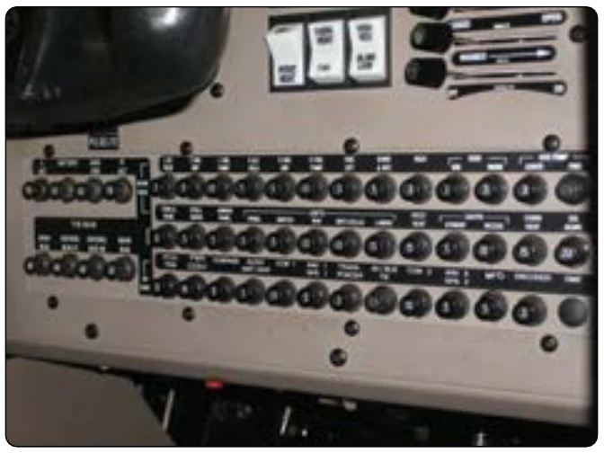
There are two ways to protect electrical systems from faults: mechanically and electrically. Mechanically, wires and components are protected from abrasion and excess wear through proper installation and by adding protective covers and shields. Electrically, wires can be protected using circuit breakers and fuses. The circuit breakers protect each system in the event of a short circuit. It should be noted that fuses can be used instead of circuit breakers. Fuses are typically found on older aircraft. A circuit breaker panel from a light aircraft is shown in Figure 9-83.
Battery Circuit
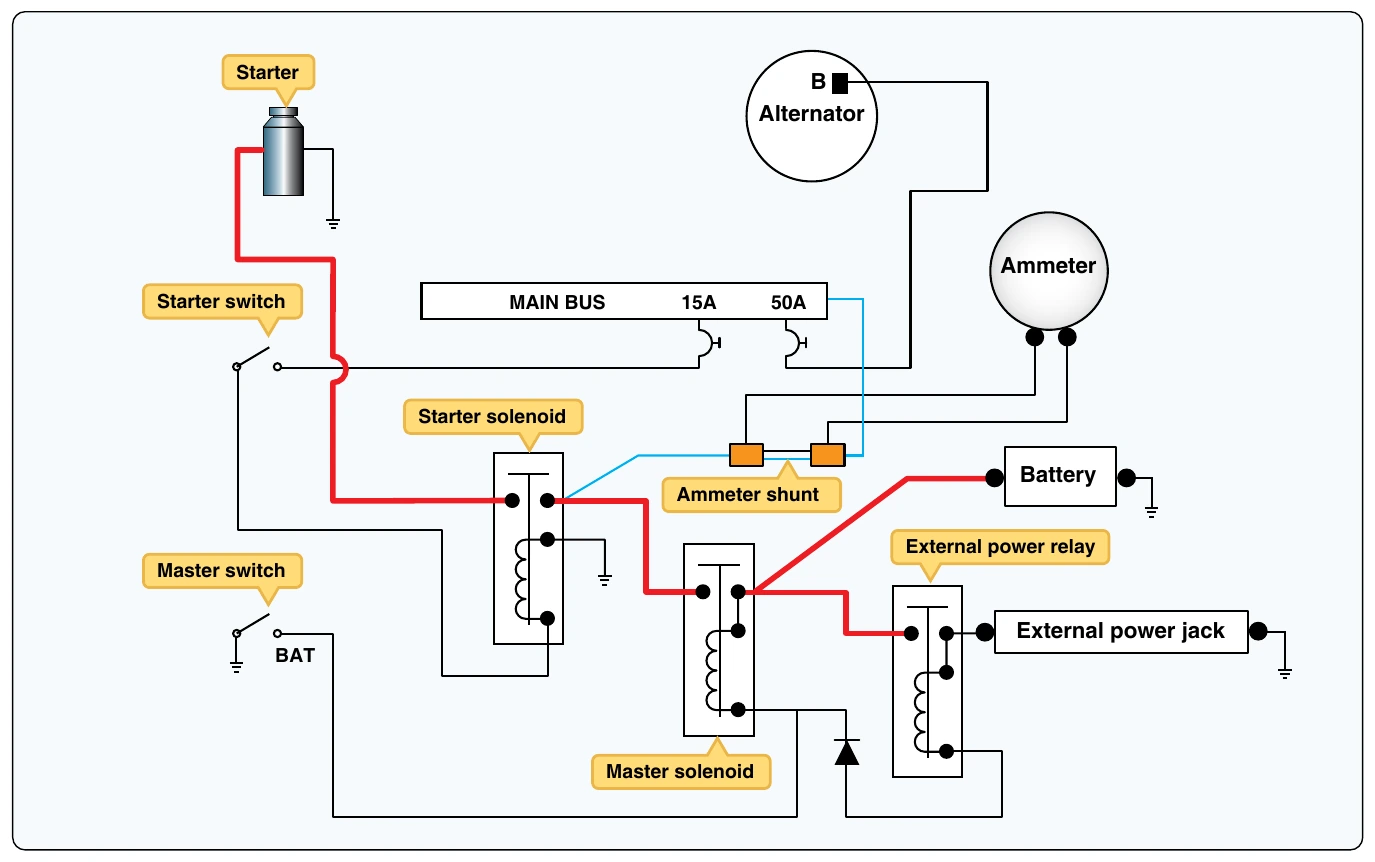
The aircraft battery and battery circuit is used to supply power for engine starting and to provide a secondary power supply in the event of an alternator (or generator) failure. A schematic of a typical battery circuit is shown in Figure 9-84. This diagram shows the relationship of the starter and external power circuits that are discussed later in this chapter. The bold lines found on the diagram represent large wire (see the wire leaving the battery positive connection), which is used in the battery circuit due to the heavy current provided through these wires. Because batteries can supply large current flows, a battery is typically connected to the system through an electrical solenoid. At the start/end of each flight, the battery is connected/disconnected from the electrical distribution bus through the solenoid contacts. A battery master switch on the flight deck is used to control the solenoid.
Although they are very similar, there is often confusion between the terms “solenoid” and “relay.” A solenoid is typically used for switching high current circuits and relays are used to control lower current circuits. To help illuminate the confusion, the term “contactor” is often used when describing a magnetically operated switch. For general purposes, an aircraft technician may consider the terms relay, solenoid, and contactor synonymous. Each of these three terms may be used on diagrams and schematics to describe electrical switches controlled by an electromagnet.
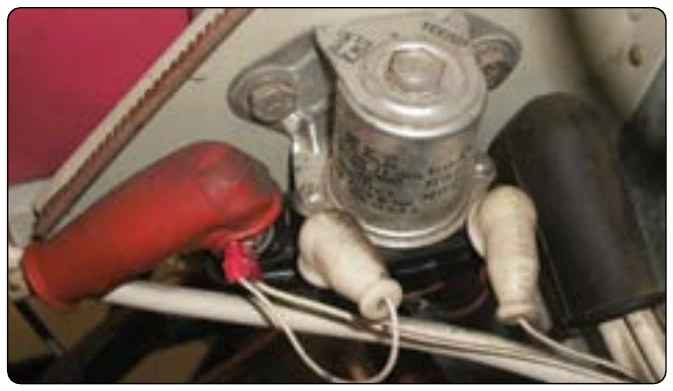
Here it can be seen that the battery positive wire is connected to the electrical bus when the battery master switch is active. A battery solenoid is shown in Figure 9-85. The battery switch is often referred to as the master switch since it turns off or on virtually all electrical power by controlling the battery connection. Note how the electrical connections of the battery solenoid are protected from electrical shorts by rubber covers at the end of each wire.
The ammeter shown in the battery circuit is used to monitor the current flow from the battery to the distribution bus. When all systems are operating properly, battery current should flow from the main bus to the battery giving a positive indication on the ammeter. In this case, the battery is being charged. If the aircraft alternator (or generator) experiences a malfunction, the ammeter indicates a negative value. A negative indication means current is leaving the battery to power any electrical load connected to the bus. The battery is being discharged and the aircraft is in danger of losing all electrical power.
Generator Circuit
Generator circuits are used to control electrical power between the aircraft generator and the distribution bus. Typically, these circuits are found on older aircraft that have not upgraded to an alternator. Generator circuits control power to the field winding and electrical power from the generator to the electrical bus. A generator master switch is used to turn on the generator typically by controlling field current. If the generator is spinning and current is sent to the field circuit, the generator produces electrical power. The power output of the generator is controlled through the generator control unit (or voltage regulator). A simplified generator control circuit is shown in Figure 9-86.
As can be seen in Figure 9-86, the generator switch controls the power to the generator field (F terminal). The generator output current is supplied to the aircraft bus through the armature circuit (A terminal) of the generator.
Alternator Circuit
Alternator circuits, like generator circuits, must control power both to and from the alternator. The alternator is controlled by the pilot through the alternator master switch. The alternator master switch in turn operates a circuit within the alternator control unit (or voltage regulator) and sends current to the alternator field. If the alternator is powered by the aircraft engine, the alternator produces electrical power for the aircraft electrical loads. The alternator control circuit contains the three major components of the alternator circuit: alternator, voltage regulator, and alternator master switch. [Figure 9-87]