
Chapter 9
Aircraft Electrical System
The voltage regulator controls the generator field current according to aircraft electrical load (alternator). If the aircraft engine is running and the alternator master switch is on, the voltage regulator adjusts current to the alternator field as needed. If more current flows to the alternator field, the alternator output increases and feeds the aircraft loads through the distribution bus.
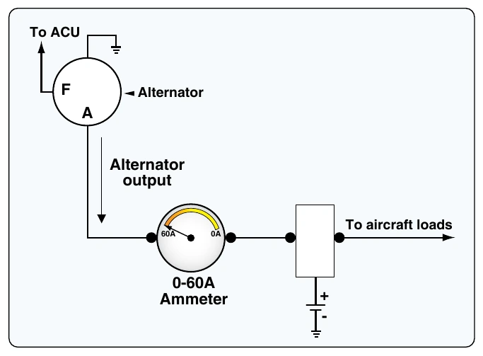
All alternators must be monitored for correct output. Most light aircraft employ an ammeter to monitor alternator output. Figure 9-88 shows a typical ammeter circuit used to monitor alternator output. An ammeter placed in the alternator circuit is a single polarity meter that shows current flow in only one direction. This flow is from the alternator to the bus. Since the alternator contains diodes in the armature circuit, current cannot reverse flow from the bus to the alternator.
When troubleshooting an alternator system, be sure to monitor the aircraft ammeter. If the alternator system is inoperative, the ammeter gives a zero indication. In this case, the battery is being discharged. A voltmeter is also a valuable tool when troubleshooting an alternator system. The voltmeter should be installed in the electrical system while the engine is running and the alternator operating. A system operating normally produces a voltage within the specified limits (approximately 14 volts or 28 volts depending on the electrical system). Consult the aircraft manual and verify the system voltage is correct. If the voltage is below specified values, the charging system should be inspected.
External Power Circuit
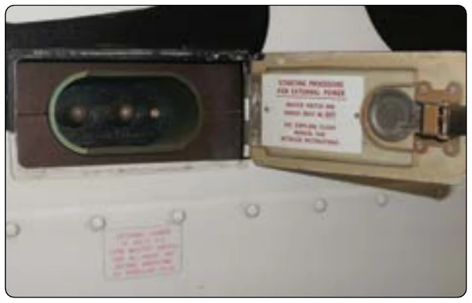
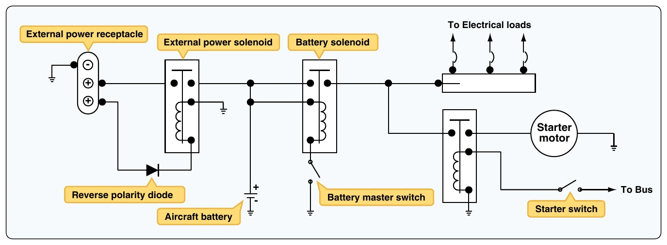
Many aircraft employ an external power circuit that provides a means of connecting electrical power from a ground source to the aircraft. External power is often used for starting the engine or maintenance activities on the aircraft. This type of system allows operation of various electrical systems without discharging the battery. The external power systems typically consists of an electrical plug located in a convenient area of the fuselage, an electrical solenoid used to connect external power to the bus, and the related wiring for the system. A common external power receptacle is shown in Figure 9-89.
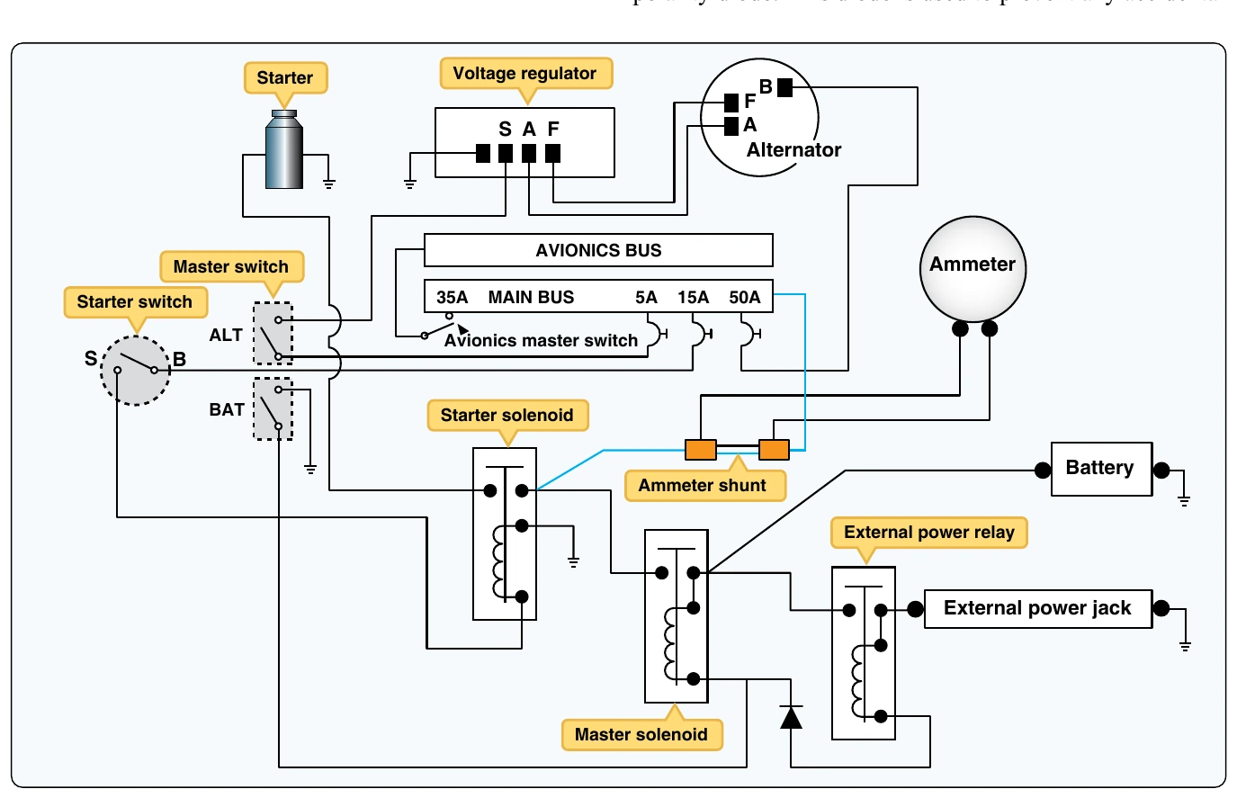
Figure 9-90 shows how the external power receptacle connects to the external power solenoid through a reverse connection in the event the external power supply has the incorrect polarity (i.e., a reverse of the positive and negative electrical connections). A reverse polarity connection could be catastrophic to the aircraft’s electrical system. If a ground power source with a reverse polarity is connected, the diode blocks current and the external power solenoid does not close. This diagram also shows that external power can be used to charge the aircraft battery or power the aircraft electrical loads. For external power to start the aircraft engine or power electrical loads, the battery master switch must be closed.
Starter Circuit
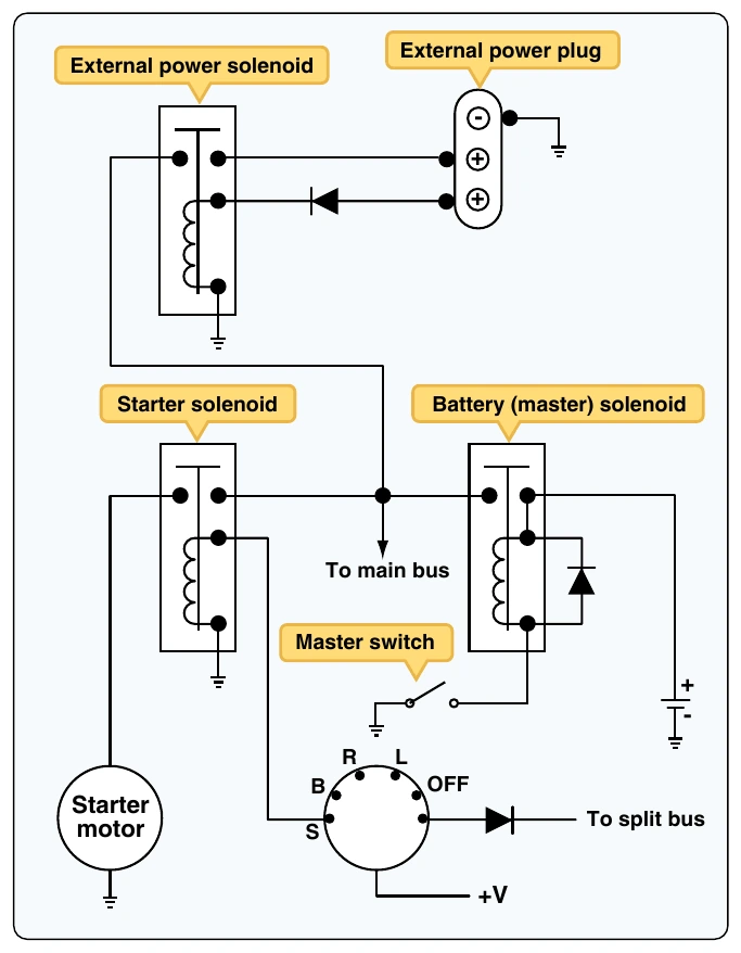
Virtually all modern aircraft employ an electric motor to start the aircraft engine. Since starting the engine requires several horsepower, the starter motor can often draw 100 or more amperes. For this reason, all starter motors are controlled through a solenoid. [Figure 9-91]
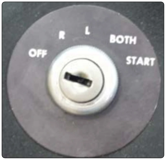
The starter circuit must be connected as close as practical to the battery since large wire is needed to power the starter motor and weight savings can be achieved when the battery and the starter are installed close to each other in the aircraft. As shown in the starter circuit diagram, the start switch can be part of a multifunction switch that is also used to control the engine magnetos. [Figure 9-92]
The starter can be powered by either the aircraft battery or the external power supply. Often when the aircraft battery is weak or in need of charging, the external power circuit is used to power the starter. During most typical operations, the starter is powered by the aircraft battery. The battery master must be on and the master solenoid closed in order to start the engine with the battery.
Avionics Power Circuit
Many aircraft contain a separate power distribution bus specifically for electronics equipment. This bus is often referred to as an avionics bus. Since modern avionics equipment employs sensitive electronic circuits, it is often advantageous to disconnect all avionics from electrical power to protect their circuits. For example, the avionics bus is often depowered when the starter motor is activated. This helps to prevent any transient voltage spikes produced by the starter from entering the sensitive avionics. [Figure 9-93]
The circuit employs a normally closed (NC) solenoid that connects the avionics bus to the main power bus. The electromagnet of the solenoid is activated whenever the starter is engaged. Current is sent from the starter switch through diode D1, causing the solenoid to open and depower the avionics bus. At that time, all electronics connected to the avionics bus will lose power. The avionics contactor is also activated whenever external power is connected to the aircraft. In this case, current travels through diodes D2 and D3 to the avionics bus contactor.