
Chapter 9
Aircraft Electrical System
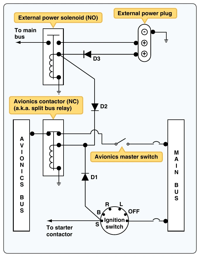
A separate avionics power switch may also be used to disconnect the entire avionics bus. A typical avionics power switch is shown wired in series with the avionics power bus. In some cases, this switch is combined with a circuit breaker and performs two functions (called a circuit breaker switch). It should also be noted that the avionics contactor is often referred to as a split bus relay, since the contactor separates (splits) the avionics bus from the main bus.
Landing Gear Circuit
Another common circuit found on light aircraft operates the retractable landing gear systems on high-performance light aircraft. These airplanes typically employ a hydraulic system to move the gear. After takeoff, the pilot moves the gear position switch to the retract position, starting an electric motor. The motor operates a hydraulic pump, and the hydraulic system moves the landing gear. To ensure correct operation of the system, the landing gear electrical system is relatively complex. The electrical system must detect the position of each gear (right, left, nose) and determine when each reaches full up or down; the motor is then controlled accordingly. There are safety systems to help prevent accidental actuation of the gear.
A series of limit switches are needed to monitor the position of each gear during the operation of the system. (A limit switch is simply a spring-loaded, momentary contact switch that is activated when a gear reaches its limit of travel.) Typically, there are six limit switches located in the landing gear wheel wells. The three up-limit switches are used to detect when the gear reaches the full retract (UP) position. Three down-limit switches are used to detect when the gear reaches the full extended (DOWN) position. Each of these switches is mechanically activated by a component of the landing gear assembly when the appropriate gear reaches a given limit.
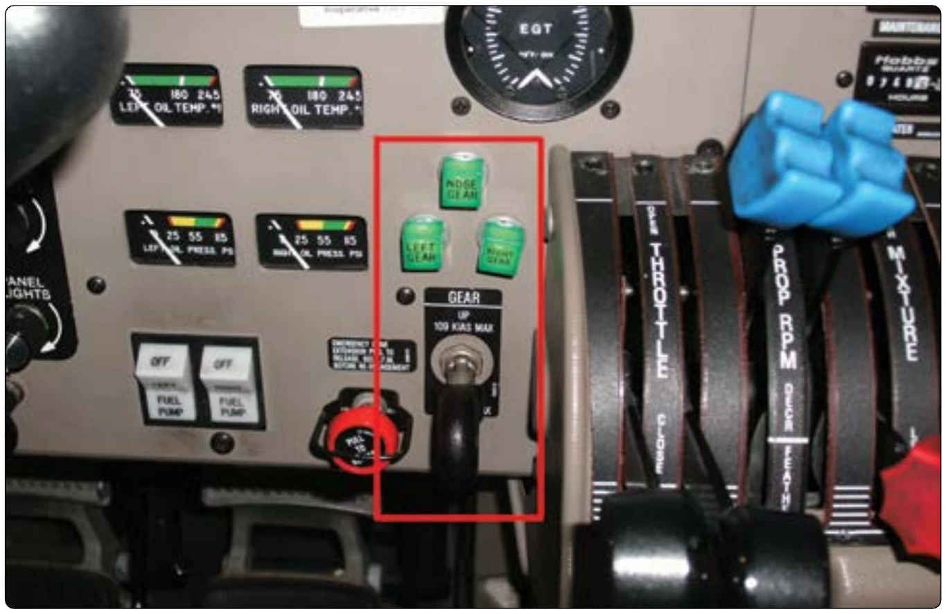
The landing gear system must also provide an indication to the pilot that the gear is in a safe position for landing. Many aircraft employ a series of three green lights when all three gears are down and locked in the landing position. These three lights are activated by the up- and down-limit switches found in the gear wheel well. A typical instrument panel showing the landing gear position switch and the three gears down indicators is shown in Figure 9-94.
The hydraulic motor/pump assembly located in the upper left corner of Figure 9-95 is powered through either the UP or DOWN solenoids (top left). The solenoids are controlled by the gear selector switch (bottom left) and the six landing gear limit switches (located in the center of Figure 9-95). The three gear DOWN indicators are individual green lights (center of Figure 9-95) controlled by the three gear DOWN switches. As each gear reaches its DOWN position, the limit switch moves to the DOWN position, and the light is illuminated.
Figure 9-95 shows the landing gear in the full DOWN position. It is always important to know gear position when reading landing gear electrical diagrams. Knowing gear position helps the technician to analyze the diagram and understand correct operation of the circuits. Another important concept is that more than one circuit is used to operate the landing gear. On this system, there is a low current control circuit fused at 5 amps (CB2, top right of Figure 9-95). This circuit is used for indicator lights and the control of the gear motor contactors. There is a separate circuit to power the gear motor fused at 30 amps (CB3, top right of Figure 9-95). Since this circuit carries a large current flow, the wires would be as short as practical and carefully protected with rubber boots or nylon insulators.
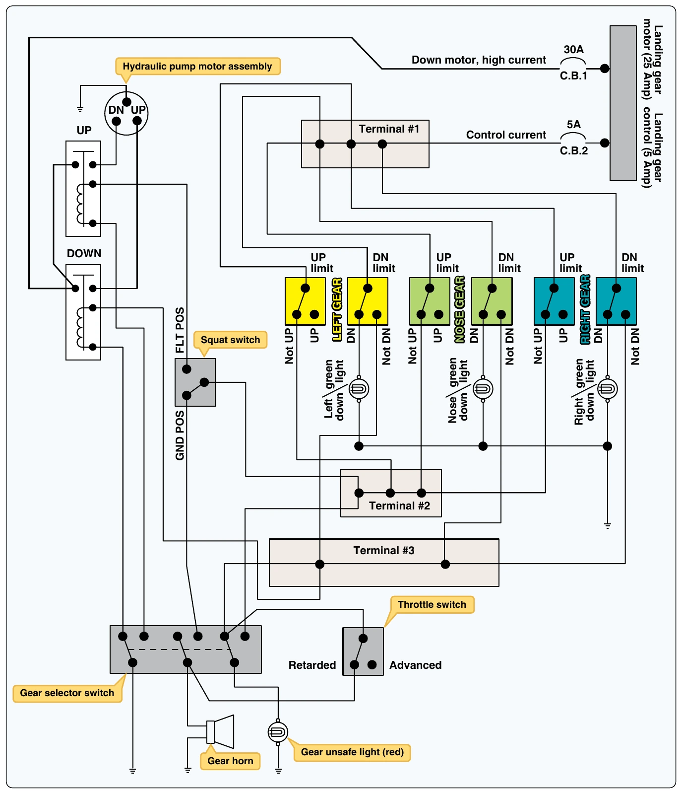
The following paragraphs describe current flow through the landing gear circuit as the system moves the gear up and down. Be sure to refer to Figure 9-96 often during the following discussions. Figure 9-96 shows current flow when the gear is traveling to the extend (DOWN) position. Current flow is highlighted in red for each description.
To run the gear DOWN motor, current must flow in the control circuit leaving CB2 through terminal 1 to the NOT DOWN contacts of the DOWN limit switches, through terminal 3, to the DOWN solenoid positive terminal (upper left). The negative side of the DOWN solenoid coil is connected to ground through the gear selector switch. Remember, the gear DOWN switches are wired in parallel and activated when the gear reach the full-DOWN position. All three gears must reach full-DOWN to shut off the gear DOWN motor. Also
When the landing gear control circuit is sending a positive voltage to the DOWN solenoid, and the gear selector switch is sending negative voltage, the solenoid magnet is energized. When the gear-DOWN solenoid is energized, the high-current gear motor circuit sends current from CB1 through the down solenoid contact points to the gear DOWN motor. When the motor runs, the hydraulic pump produces pressure and the gear begins to move. When all three gears reach the DOWN position, the gear-DOWN switches move to the DOWN position, the three green lights illuminate, and the gear motor turns off completing the gear-DOWN cycle.
Figure 9-97 shows the landing gear electrical diagram with the current flow path shown in red as the gear moves to the retract (UP) position. Starting in the top right corner of the diagram, current must flow through CB2 in the control circuit through terminal 1 to each of the three gear-UP switches. With the gear-UP switches in the not UP position, current flows to terminal 2 and eventually through the squat switch to the UP solenoid electromagnet coil. The UP solenoid coil receives negative voltage through the gear selector switch. With the UP solenoid coil activated, the UP solenoid closes and power travels through the motor circuit. To power the motor, current leaves the bus through CB1 to the terminal at the DOWN solenoid onward through the UP solenoid to the UP motor. (Remember, current cannot travel through the DOWN solenoid at this time since the DOWN solenoid is not activated.) As the UP motor runs, each gear travels to the retract position. As this occurs, the gear UP switches move from the NOT UP position to the UP position. When the last gear reaches up, the current no longer travels to terminal 2 and the gear motor turns off. It should be noted that similar to DOWN, the gear switches are wired in parallel, which means the gear motor continues to run until all three gear reach the required position.
During both the DOWN and UP cycles of the landing gear operation, current travels from the limit switches to terminal
- From terminal 2, there is a current path through the gear selector switch to the gear unsafe light. If the gear selector disagrees with the current gear position (e.g., gear is DOWN and pilot has selected UP), the unsafe light is illuminated.
The gear unsafe light is shown at the bottom of Figure 9-96.
The squat switch (shown mid left of Figure 9-96) is used to determine if the aircraft is on the GROUND or in FLIGHT. This switch is located on a landing gear strut. When the weight of the aircraft compresses the strut, the switch is activated and moved to the GROUND position. When the switch is in the GROUND position, the gear cannot be retracted and a warning horn sounds if the pilot selects gear UP. The squat switch is sometimes referred to as the weight-on-wheels switch.
A throttle switch is also used in conjunction with landing gear circuits on most aircraft. If the throttle is retarded (closed) beyond a certain point, the aircraft descends and eventually lands. Therefore, many manufacturers activate a throttle switch whenever engine power is reduced. If engine power is reduced too low, a warning horn sounds telling the pilot to lower the landing gear. Of course, this horn need not sound if the gear is already DOWN or the pilot has selected the DOWN position on the gear switch. This same horn also sounds if the aircraft is on the ground, and the gear handle is moved to the UP position. Figure 9-96 shows the gear warning horn in the bottom left corner.