
Chapter 9
Aircraft Electrical System
The type of conductor insulation material varies with the type of installation. Characteristics should be chosen based on environment, such as abrasion resistance, arc resistance, corrosion resistance, cut-through strength, dielectric strength, flame resistant, mechanical strength, smoke emission, fluid resistance, and heat distortion. Such types of insulation materials (e.g., PVC/nylon, Kapton®, and Teflon®) are no longer used for new aircraft designs, but might still be installed on older aircraft. Insulation materials for new aircraft designs are made of Tefzel®, Teflon®/Kapton®/Teflon® and PTFE/Polyimide/PTFE. The development of better and safer insulation materials is ongoing.
Since electrical wire may be installed in areas where inspection is infrequent over extended periods of time, it is necessary to give special consideration to heat-aging characteristics in the selection of wire. Resistance to heat is of primary importance in the selection of wire for aircraft use, as it is the basic factor in wire rating. Where wire may be required to operate at higher temperatures due either to high ambient temperatures, high current loading, or a combination of the two, selection should be made on the basis of satisfactory performance under the most severe operating conditions.
Wire Shielding
With the increase in number of highly sensitive electronic devices found on modern aircraft, it has become very important to ensure proper shielding for many electric circuits. Shielding is the process of applying a metallic covering to wiring and equipment to eliminate electromagnetic interference (EMI). EMI is caused when electromagnetic fields (radio waves) induce high frequency (HF) voltages in a wire or component. The induced voltage can cause system inaccuracies or even failure.
Use of shielding with 85 percent coverage or greater is recommended. Coaxial, triaxial, twinaxial, or quadraxial cables should be used, wherever appropriate, with their shields connected to ground at a single point or multiple points, depending upon the purpose of the shielding. [Figure 9-113] The airframe grounded structure may also be used as an EMI shield.
Wire Substitutions
When a replacement wire is required in the repair and modification of existing aircraft, the maintenance manual for that aircraft must first be reviewed to determine if the original aircraft manufacturer (OAM) has approved any substitution. If not, then the manufacturer must be contacted for an acceptable replacement.
Areas Designated as Severe Wind & Moisture Problem (SWAMP)
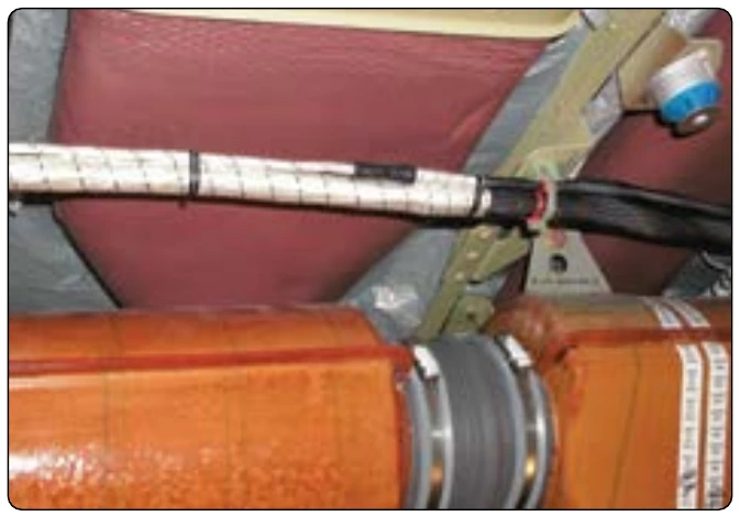
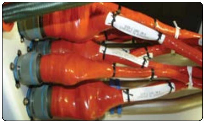
SWAMP areas differ from aircraft to aircraft but are usually wheel wells, near wing flaps, wing folds, pylons, and other exterior areas that may have a harsh environment. Wires in these areas have often an exterior jacket to protect them from the environment. Wires for these applications often have design features incorporated into their construction that may make the wire unique; therefore, an acceptable substitution may be difficult, if not impossible, to find. It is very important to use the wire type recommended in the aircraft manufacturer’s maintenance handbook. Insulation or jacketing varies according to the environment. [Figure 9-114]
Wire Size Selection
Wire is manufactured in sizes according to a standard known as the American wire gauge (AWG). As shown in Figure 9-115, the wire diameters become smaller as the gauge numbers become larger. Typical wire sizes range from a number 40 to number 0000.
Gauge numbers are useful in comparing the diameter of wires, but not all types of wire or cable can be measured accurately with a gauge. A wire gauge tool may be used to determine the size of an unmarked wire. Larger wires are usually stranded to increase their flexibility. In such cases, the total area can be determined by multiplying the area of one strand (usually computed in circular mils when diameter or gauge number is known) by the number of strands in the wire or cable.
Several factors must be considered in selecting the size of wire for transmitting and distributing electric power.
- Wires must have sufficient mechanical strength to allow for service conditions.
- Allowable power loss (I2 R loss) in the line represents electrical energy converted into heat. The use of large conductors reduces the resistance and therefore the I2 R loss. However, large conductors are more expensive,
heavier, and need more substantial support.
- If the source maintains a constant voltage at the input to the lines, any variation in the load on the line causes a variation in line current and a consequent variation in the IR drop in the line. A wide variation in the IR drop in the line causes poor voltage regulation at the load. The obvious remedy is to reduce either current or resistance. A reduction in load current lowers the amount of power being transmitted, whereas a reduction in line resistance increases the size and weight of conductors required. A compromise is generally reached whereby the voltage variation at the load is within tolerable limits and the weight of line conductors is not excessive.
- When current is drawn through the conductor, heat is generated. The temperature of the wire rises until the heat radiated, or otherwise dissipated, is equal to the heat generated by the passage of current through the line. If the conductor is insulated, the heat generated in the conductor is not so readily removed as it would be if the conductor were not insulated. Thus, to protect the insulation from too much heat, the current through the conductor must be maintained below a certain value. When electrical conductors are installed in locations where the ambient temperature is relatively high, the heat generated by external sources constitutes an appreciable part of the total conductor heating. Allowance must be made for the influence of external heating on the allowable conductor current, and each case has its own specific limitations. The maximum allowable operating temperature of insulated conductors varies with the type of conductor insulation being used.
If it is desirable to use wire sizes smaller than #20, particular attention should be given to the mechanical strength and installation handling of these wires (e.g., vibration, flexing, and termination). Wires containing less than 19 strands must not be used. Consideration should be given to the use of high-strength alloy conductors in small-gauge wires to increase mechanical strength. As a general practice, wires smaller than size #20 should be provided with additional clamps and be grouped with at least three other wires. They should also have additional support at terminations, such as connector grommets, strain relief clamps, shrinkable sleeving, or telescoping bushings. They should not be used in applications where they are subjected to excessive vibration, repeated bending, or frequent disconnection from screw termination. [Figure 9-116]