
Chapter 9
Aircraft Electrical System
Split-Parallel Systems
A split-parallel bus basically employs the best of both split-bus and the parallel-bus systems. The split-parallel system is found on the Boeing 747-400 and contains four generators driven by the main engines and two APU-driven generators. The system can operate with all generators in parallel, or the generators can be operated independently as in a split-bus system. During a normal flight, all four engine-driven generators are operated in parallel. The system is operated in split-bus mode only under certain failure conditions or when using external power. The Boeing 747-400 split-parallel system is computer controlled using four GCUs and two BPCUs. There is one GCU controlling each generator; BPCU 1 controls the left side bus power distribution, and BPCU 2 controls the right side bus power. The GCUs and BPCUs operate similarly to those previously discussed under the split-bus system.
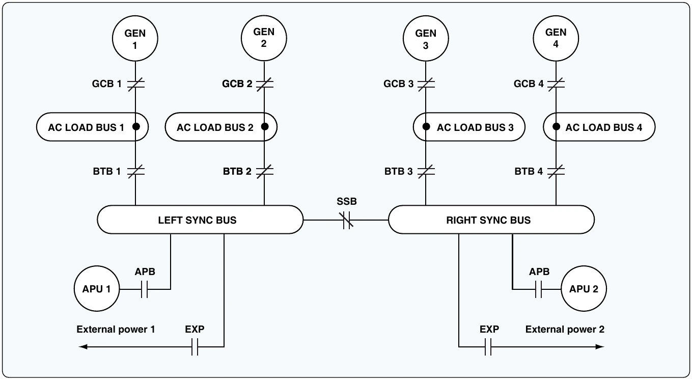
Figure 9-106 shows a simplified split-parallel power distribution system. The main generators (top of Figure 9-106) are driven by the main turbine engines. Each generator is connected to its load bus through a generator control breaker (GCB). The generator control unit closes the GCB when the pilot calls for generator power and all systems are operating normally. Each load bus is connected to various electrical systems and additional sub-buses. The BTBs are controlled by the BPCU and connect each load bus to the left and right sync bus. A split systems breaker (SSB) is used to connect the left and right sync buses and is closed during a normal flight. With the SSB, GCBs, and BTBs, in the closed position the generators operate in parallel. When operating in parallel, all generators must be in phase.
If the aircraft electrical system experiences a malfunction, the control units make the appropriate adjustments to ensure all necessary loads receive electrical power. For example, if generator 1 fails, GCU 1 detects the fault and commands GCB 1 to open. With GCB 1 open, load bus 1 now feeds from the sync bus and the three operating generators. In another example, if load bus 4 should short to ground, BPCU 4 opens the GCB 4 and BTB 4. This isolates the shorted bus (load bus 4). All loads on the shorted bus are no longer powered, and generator 4 is no longer available. However, with three remaining generators operational, the flight continues safely.
As do all large aircraft, the Boeing 747-400 contains a DC power distribution system. The DC system is used for battery and emergency operations. The DC system is similar to those previously discussed, powered by TR units. The TRs are connected to the AC buses and convert AC into 26-volt DC. The DC power systems are the final backups in the event of a catastrophic electrical failure. The systems most critical to fly the aircraft can typically receive power from the battery. This aircraft also contains two static inverters to provide emergency AC power when needed.
Wiring Installation
Wiring Diagrams
Electrical wiring diagrams are included in most aircraft service manuals and specify information, such as the size of the wire and type of terminals to be used for a particular application. Furthermore, wiring diagrams typically identify each component within a system by its part number and its serial number, including any changes that were made during the production run of an aircraft. Wiring diagrams are often used for troubleshooting electrical malfunctions.
Block Diagrams
A block diagram is used as an aid for troubleshooting complex electrical and electronic systems. A block diagram consists of individual blocks that represent several components, such as a printed circuit board or some other type of replaceable module. Figure 9-107 is a block diagram of an aircraft electrical system.
Pictorial Diagrams
In a pictorial diagram, pictures of components are used instead of the conventional electrical symbols found in schematic diagrams. A pictorial diagram helps the maintenance technician visualize the operation of a system. [Figure 9-108]
Schematic Diagrams
A schematic diagram is used to illustrate a principle of operation, and therefore does not show parts as they actually appear or function. [Figure 9-109] However, schematic diagrams do indicate the location of components with respect to each other. Schematic diagrams are best utilized for troubleshooting.
Wire Types
The satisfactory performance of any modern aircraft depends to a very great degree on the continuing reliability of electrical systems and subsystems. Improperly or carelessly maintained wiring can be a source of both immediate and potential danger. The continued proper performance of electrical systems depends on the knowledge and techniques of the technician who installs, inspects, and maintains the electrical system wires and cables.
Procedures and practices outlined in this section are general recommendations and are not intended to replace the manufacturer’s instructions and approved practices.
A wire is described as a single, solid conductor, or as a stranded conductor covered with an insulating material. Figure 9-110 illustrates these two definitions of a wire. Because of in-flight vibration and flexing, conductor round wire should be stranded to minimize fatigue breakage.
The term “cable,” as used in aircraft electrical installations, includes: