Step 3—Derate the size 22 free air rating by multiplying 16.2 by 0.52 to get 8.4 amps in harness rating. Derate the size 20 free air rating by multiplying 21.5 by 0.52 to get 11.2 amps in-harness rating.
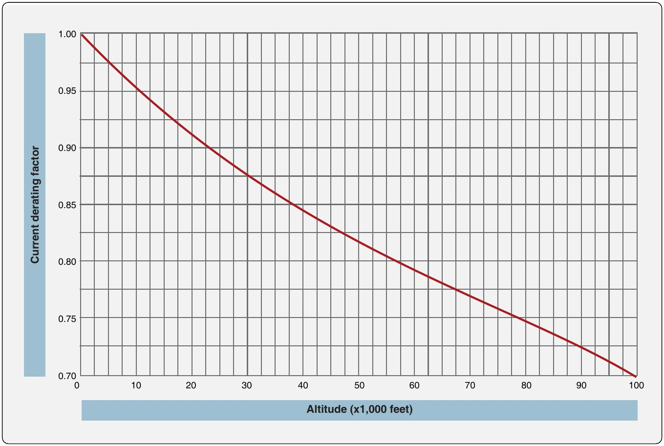
Step 4—Refer to the altitude derating curve in Figure 9-119. Look for 35,000 feet (on the horizontal axis) since that is the altitude at which the aircraft is operating. Note that the wire must be derated by a factor of 0.86 (found on the vertical axis). Derate the size 22 harness rating by multiplying 8.4 amps by 0.86 to get 7.2 amps. Derate the size 20 harness rating by multiplying 11.2 amps by 0.86 to get 9.6 amps.
Formula: Step 5—To find the total harness capacity, multiply the ; total number of size 22 wires by the derated capacity ; (25 × 7.2 = 180.0 amps) and add to that the number of size ; 20 wires multiplied by the derated capacity (10 × 9.6 = ; 96.8 amps) and multiply the sum by the 20 percent harness ; capacity factor. Thus, the total harness capacity is (180.0 + ; 96.0) × 0.20 = 55.2 amps. It has been determined that the ; total harness current should not exceed 55.2 A, size 22 wire ; should not carry more than 7.2 amps and size 20 wire should
not carry more than 9.6 amps.
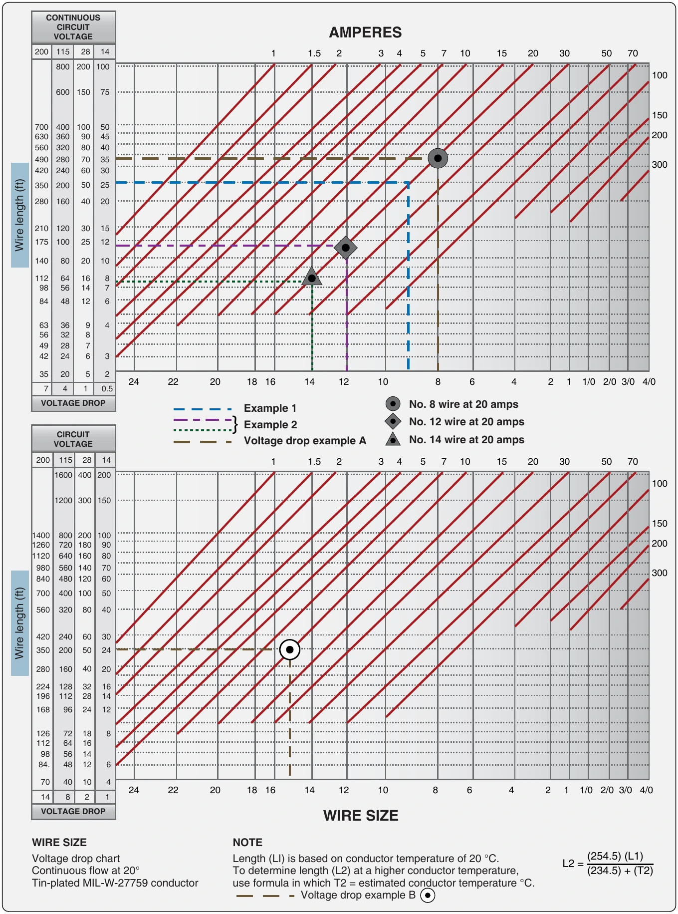
Figure 9-116. Conductor chart, continuous (top) and intermittent flow (bottom).
Formula: Figure 9-116 formula reference: Copper-wire sizing and voltage-drop chart for continuous and intermittent loads. Temperature correction is L2 = (254.5 × L1) / (234.5 + T2), where L1 is chart length at 20 °C, L2 is allowable length at conductor temperature T2 in °C. Source text: CONTINUOUS ; CIRCUIT VOLTAGE AMPERES ; 200 115 28 14 1 1.5 2 3 4 5 7 10 15 20 30 50 70 ; 800 200 100 ; 100 ; 600 150 75 ; 150 ; 700 400 100 50 ; 630 360 90 45 200 ; 560 320 80 40 ; 4 4 9 2 0 0 2 2 8 4 0 0 7 6 0 0 3 3 5 0 300 ; 350 200 50 25 ; Wire length (ft) ; 280 160 40 20 ; 210 120 30 15 ; 175 100 25 12 ; 140 80 20 10 ; 112 64 16 8 ; 98 56 14 7 ; 84 48 12 6 ; ......!......................................................... ; ::::::r::.:::::::::::::::::::::::::::::::::::::::::::::::::::::: ; 63 36 9 4 ; 56 32 8 ; ······t·····.·.·.·.·............................................ ; 49 28 7 42 24 6 3 ; ······1·························································· ; 35 20 5 2 ; 24 22 20 18 16 14 12 10 8 6 4 2 1 1/0 2/0 3/0 ; 4/0 ; 7 4 1 0.5 ; VOLTAGE DROP No. 8 wire at 20 amps ; Example 1 ; Example 2 No. 12 wire at 20 amps ; CIRCUIT VOLTAGE Voltage drop example A No. 14 wire at 20 amps ; 200 115 28 14 1 1.5 2 3 4 5 7 10 15 20 30 50 70 ; 1600 400 200 ; 100 ; 1200 300 150 ; 150 ; 1400 800 200 100 ; 1260 720 180 90 200 ; 1120 640 160 80 ; 9 8 8 4 0 0 5 4 6 8 0 0 1 1 4 2 0 0 7 6 0 0 300 ; 700 400 100 50 ; Wire length (ft) ; 560 320 80 40 ; 420 240 60 30 ; 350 200 50 24 ; 280 160 40 20 ; 224 128 32 16 ; 196 112 28 14 ; 168 96 24 12 ; 126 72 18 8 ··.·.::::::.:.::::::::::::::::::::::::::·:::::::::1:::::::::::::::::: ; 112 64 16...............................·.·.·.·.·.·.·.·.·.l ················· ; 8 9 4 8. 5 4 6 8 1 1 4 2 6 ··················································r·--·············· ; 70 40 10 4 ; 24 22 20 18 16 14 12 10 8 6 4 2 1 1/0 2/0 3/0 4/0 ; 14 8 2 1 ; VOLTAGE DROP WIRE SIZE ; WIRE SIZE NOTE ; Voltage drop chart Length (L1) is based on conductor temperature of 20 °C. L2 = (254.5) (L1) ; Continuous flow at 20° To determine length (L2) at a higher conductor temperature, (234.5) + (T2) ; Tin-plated MIL-W-27759 conductor use formula in which T2 = estimated conductor temperature °C. ; Voltage drop example B
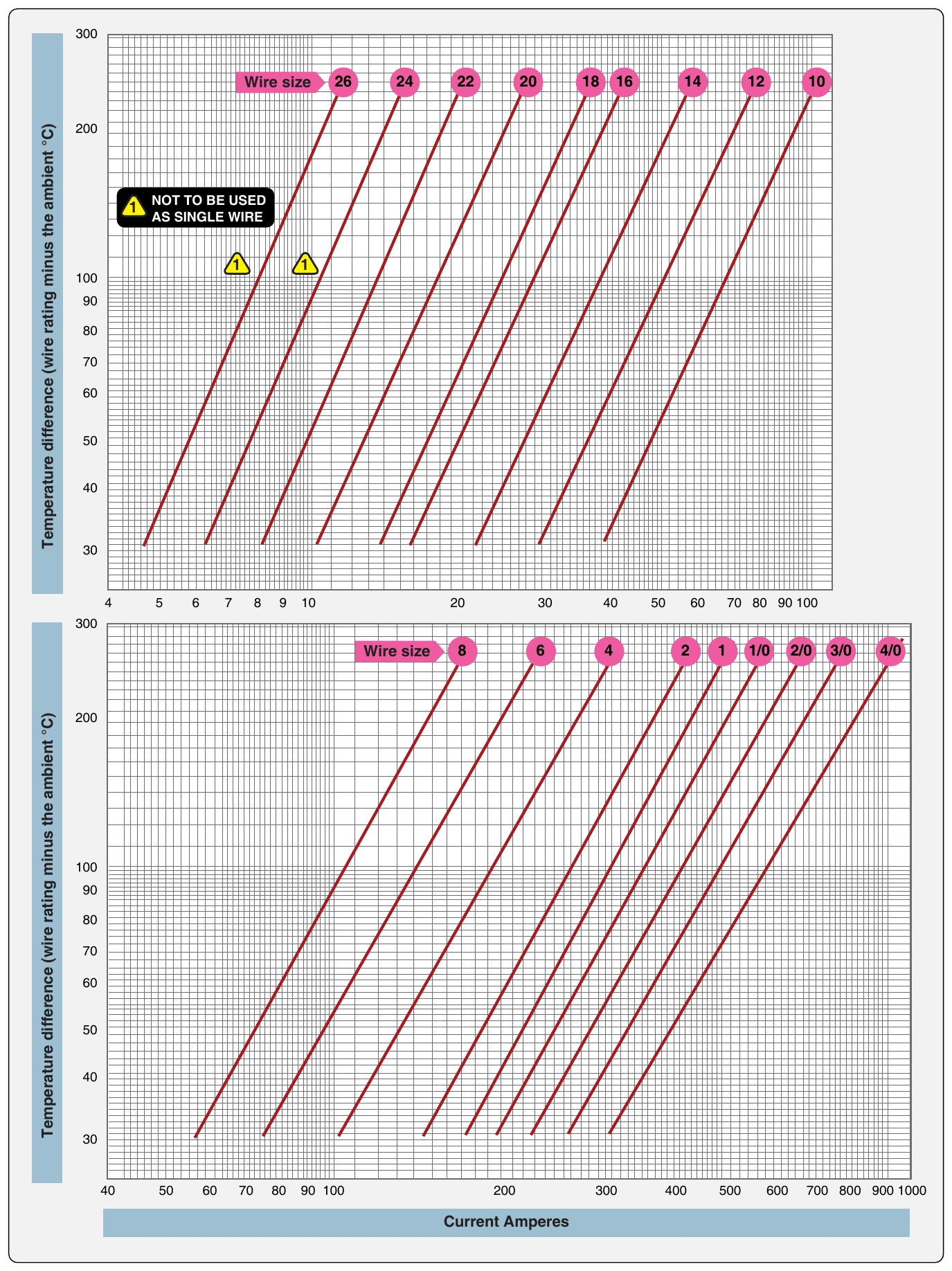
Figure 9-117. Single copper wire in free air.
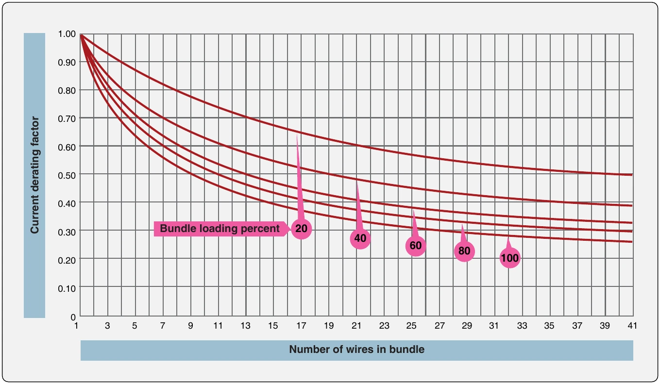
Figure 9-118. Bundle derating curve.
Formula: Figure 9-118 formula reference: Bundle derating chart: select the curve for bundle loading percentage, use the number of wires in the bundle, and read the current-capacity derating factor. Source text: 1.00 \ ; r--........ ; 0 ; . ; 9 ; 0 ; r ; - ; -' ; '~ ; .......,................. ; '~ ; 0 ; . ; 8 ; 0 ; I" ; - ; 0 0 0 0.... 7 6 5 4 0 0 0 0 " r--.. ' -.... ' 1.. '..,............................... r........-.....,..... r r..... - -...... - -.. - -.. - -......... - I. -'..-...-. --... r.... -.... -.......--...........-,,...................... -...... - -..... - i -. -.. r.. - •.... -.. - - - ; Current capacity derating ; """ • ; factor ; 0.30 Bundle loading percent 20 40 t 60. 8 I 0 - -- ; 0.20 100 ; 0.10 ; 0 ; 1 3 5 7 9 11 13 15 17 19 21 23 25 27 29 31 33 35 37 39 41 ; Number of wires in bundle
Figure 9-119. Altitude derating curve.
Formula: Figure 9-119 formula reference: Altitude derating chart: use altitude from sea level to 100,000 feet to obtain the current-capacity derating factor, approximately 1.00 at sea level and 0.70 at 100,000 feet. Source text: 1.00 r\ ; i\ ; " ; r\ ', ; 0.95 ; ... ; r--... ; ' ; 0.90 "'r-,... ; Current capacity derating ; ' ; ' r--..., ; ' ; 0.85...., ; ... ; I...._....... ; ........... ; factor ; 0.80............. ; ............ ; ..... ; .................... ; 0.75...... ; ................. ; .............. ; ........... ; 0.70 ; 0 10 20 30 40 50 60 70 80 90 100 ; Altitude (x1,000 feet)
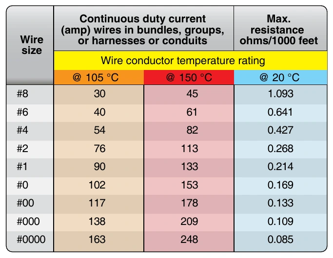
Figure 9-120. Current-carrying capacity and resistance of aluminum wire.
Formula: Figure 9-120 formula reference: Aluminum-wire reference: continuous-duty current at 105 °C and 150 °C, plus maximum resistance at 20 °C, for sizes AWG 8 through 0000. Source text: Continuous duty current Max. ; (amp) wires in bundles, groups, resistance ; Wire or harnesses or conduits ohms/1000 feet ; size ; Wire conductor temperature rating ; @ 105 °C @ 150 °C @ 20 °C ; #8 30 45 1.093 ; #6 40 61 0.641 ; #4 54 82 0.427 ; #2 76 113 0.268 ; #1 90 133 0.214 ; #0 102 153 0.169 ; #00 117 178 0.133 ; #000 138 209 0.109 ; #0000 163 248 0.085
Step 6—Determine the actual circuit current for each wire in the bundle and for the whole bundle. If the values calculated in step 5 are exceeded, select the next larger size wire and repeat the calculations.
Example 2 Assume a harness (open or braided), consisting of 12 size 12, 200 °C rated copper wires, is operated in an ambient temperature of 25 °C at sea level and 60 °C at a 20,000-foot altitude. All 12 wires are operated at or near their maximum capacity.
Step 1—Refer to the single wire in free air curve in Figure 9-117, determine the temperature difference of the wire to determine free air ratings. Since the wire is in ambient
Formula: temperature of 25 °C and 60 °C and is rated at 200 °C, the ; temperature differences are 200 °C – 25 °C = 175 °C and ; 200 °C – 60 °C = 140 °C, respectively. Follow the 175 °C ; and the 140 °C temperature difference lines on Figure 9-116
until each intersects wire size line. The free air ratings of size 12 are 68 amps and 59 amps, respectively.
Step 2—Refer to the bundling derating curves in Figure 9-118. The 100 percent curve is selected because we know all 12 wires are carrying full load. Find 12 (on the horizontal axis) since there are 12 wires in the bundle and determine a derating factor of 0.43 (on the vertical axis) from the 100 percent curve.
Step 3—Derate the size #12 free air ratings by multiplying 68 amps and 61 amps by 0.43 to get 29.2 amps and 25.4 amps, respectively.
Cookie Preferences
We use cookies to operate this website, improve performance, understand site traffic, and personalize your experience. Essential cookies are always active because they are required for the website to function.
Required for basic site functionality and security.
Help us understand how visitors use the website so we can improve it.
May be used for advertising, remarketing, or social media features.
You can update your choices anytime using Cookie Settings. View Privacy Policy