
Chapter 9
Aircraft Electrical System
Wires, or groups of wires, should enter a junction box, or terminate at a piece of equipment in an upward direction where practicable. Ensure that a trap, or drip loop, is provided to prevent fluids or condensation from running into wire or cable ends that slope downward toward a connector, terminal block, panel, or junction block. A drip loop is an area where the wire(s) are made to travel downward and then up to the connector. [Figure 9-134] Fluids and moisture will flow along the wires to the bottom of the loop and be trapped there to drip or evaporate without affecting electrical conductivity in the wire, junction, or connected device.
Where wires must be routed downwards to a junction box or electrical unit and a drip loop is not possible, the entrance should be sealed according to manufacturer’s specifications to prevent moisture from entering the box/unit. Wires and cables installed in bilges and other locations where fluids collect must be routed as far from the lowest point as possible or otherwise be provided with a moisture-proof covering.
Protection of Wires in Wheel Well Areas
Wires located on landing gear and in the wheel well area can be exposed to many hazardous conditions if not suitably protected. Where wire bundles pass flex points, there must not be any strain on attachments or excessive slack when parts are fully extended or retracted. The wiring and protective tubing must be inspected frequently and replaced at the first sign of wear.
Wires should be routed so that fluids drain away from the connectors. When this is not practicable, connectors must be potted. Wiring which must be routed in wheel wells or other external areas must be given extra protection in the form of harness jacketing and connector strain relief. Conduits or flexible sleeving used to protect wiring must be equipped with drain holes to prevent entrapment of moisture.
The technician should check during inspections that wires and cables are adequately protected in wheel wells and other areas where they may be exposed to damage from impact of rocks, ice, mud, etc. (If rerouting of wires or cables is not practical, protective jacketing may be installed). This type of installation must be held to a minimum.
Clamp Installation
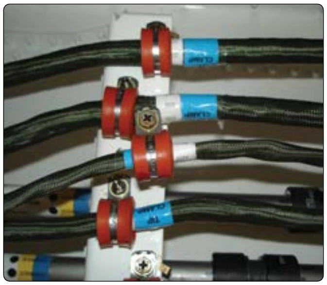
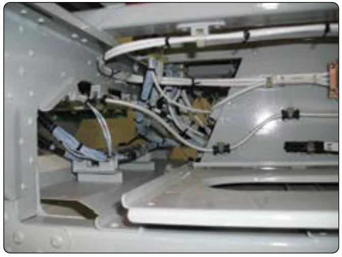
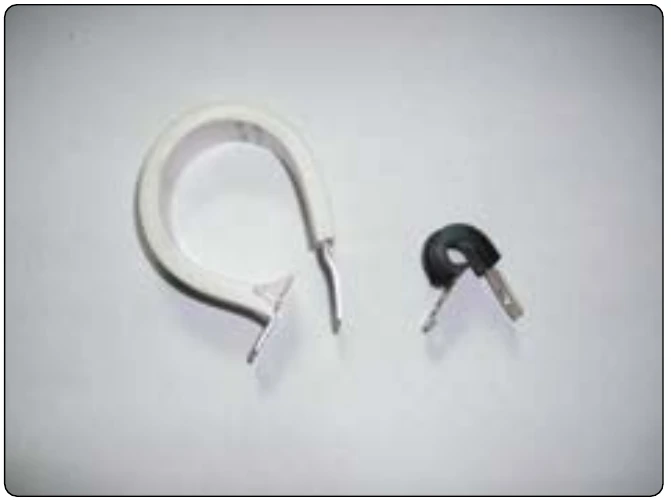
Wires and wire bundles must be supported by clamps or plastic cable straps. [Figure 9-135] Clamps and other primary support devices must be constructed of materials that are compatible with their installation and environment, in terms of temperature, fluid resistance, exposure to ultraviolet (UV) light, and wire bundle mechanical loads. They should be spaced at intervals not exceeding 24 inches. Clamps on wire bundles should be selected so that they have a snug fit without pinching wires. [Figures 9-136 through 9-138]
Caution: The use of metal clamps on coaxial RF cables may cause problems, if clamp fit is such that RF cable’s original cross section is distorted.
Clamps on wire bundles should not allow the bundle to move through the clamp when a slight axial pull is applied. Clamps on RF cables must fit without crushing and must be snug enough to prevent the cable from moving freely through the clamp, but may allow the cable to slide through the clamp when a light axial pull is applied. The cable or wire bundle may be wrapped with one or more turns of electrical tape when required to achieve this fit. Plastic clamps or cable ties must not be used where their failure could result in interference with movable controls, wire bundle contact with movable equipment, or chafing damage to essential or unprotected wiring. They must not be used on vertical runs where inadvertent slack migration could result in chafing or other damage. Clamps must be installed with their attachment hardware positioned above them, wherever practicable, so that they are unlikely to rotate as the result of wire bundle weight or wire bundle chafing. [Figure 9-136]
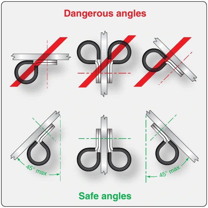
Clamps lined with nonmetallic material should be used to support the wire bundle along the run. Tying may be used between clamps, but should not be considered as a substitute for adequate clamping. Adhesive tapes are subject to age deterioration and, therefore, are not acceptable as a clamping means. [Figure 9-137]
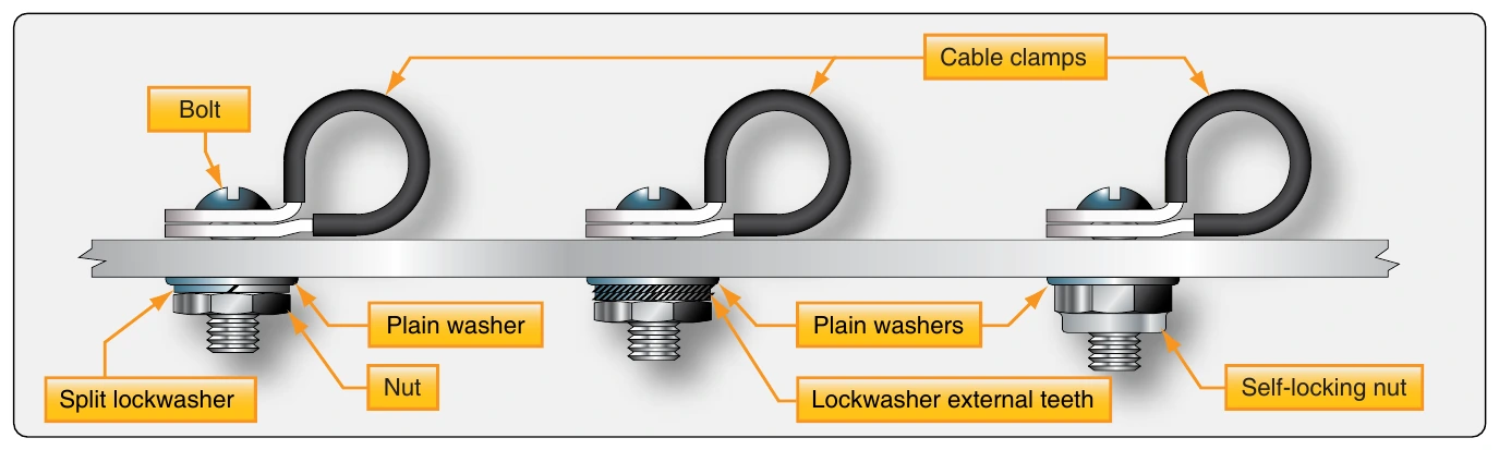
The back of the clamp, whenever practical, should be rested against a structural member. [Figure 9-138] Stand-offs should be used to maintain clearance between the wires and the structure. Clamps must be installed in such a manner that the electrical wires do not come in contact with other parts of the aircraft when subjected to vibration. Sufficient slack should be left between the last clamp and the electrical equipment to prevent strain at the terminal and to minimize adverse effects on shock-mounted equipment. Where wires or wire bundles pass through bulkheads or other structural members, a grommet or suitable clamp should be provided to prevent abrasion.
When a wire bundle is clamped into position, if there is less than 3⁄8-inch of clearance between the bulkhead cutout and the wire bundle, a suitable grommet should be installed as indicated in Figure 9-139. The grommet may be cut at a 45° angle to facilitate installation, provided it is cemented in place and the slot is located at the top of the cutout.
Wire & Cable Clamp Inspection
Inspect wire and cable clamps for proper tightness. Where cables pass through structure or bulkheads, inspect for proper clamping and grommets. Inspect for sufficient slack between the last clamp and the electronic equipment to prevent strain at the cable terminals and to minimize adverse effects on shock-mounted equipment. Wires and cables are supported by suitable clamps, grommets, or other devices at intervals of not more than 24 inches, except when contained in troughs, ducts, or conduits. The supporting devices should be of a suitable size and type, with the wires and cables held securely in place without damage to the insulation.