
Chapter 9
Aircraft Electrical System
Types of Wire Markings
The preferred method is to mark directly on the wire without causing insulation degradation. Teflon-coated wires, shielded wiring, multiconductor cable, and thermocouple wires usually require special sleeves to carry identification marks. There are some special wire marking machines available that can be used to stamp directly on the type wires mentioned above. Whatever method of marking is used, the marking should be legible and the color should contrast with the wire insulation or sleeve.
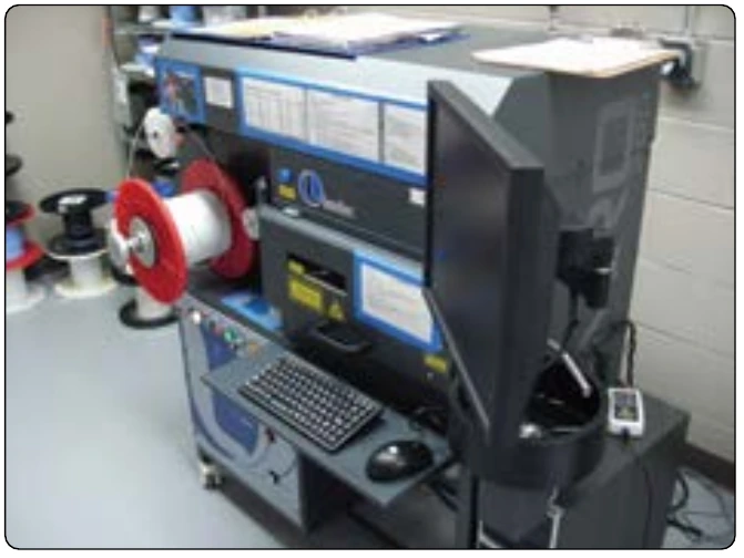
Several different methods can be used to mark directly on the wire: hot stamp marking, ink jet printers, and laser jet printers. [Figure 9-126] The hot stamp method can damage the insulation of a newer type of wire that utilizes thin insulators. Fracture of the insulation wall and penetration to the conductor of these materials by the stamping dies have occurred. Later in service, when these openings have been wetted by various fluids or moisture, serious arcing and surface tracking have damaged wire bundles.
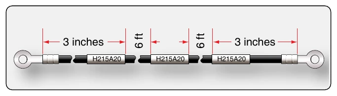
Identification sleeves can be used if the direct marking on the wire is not possible. [Figure 9-127]
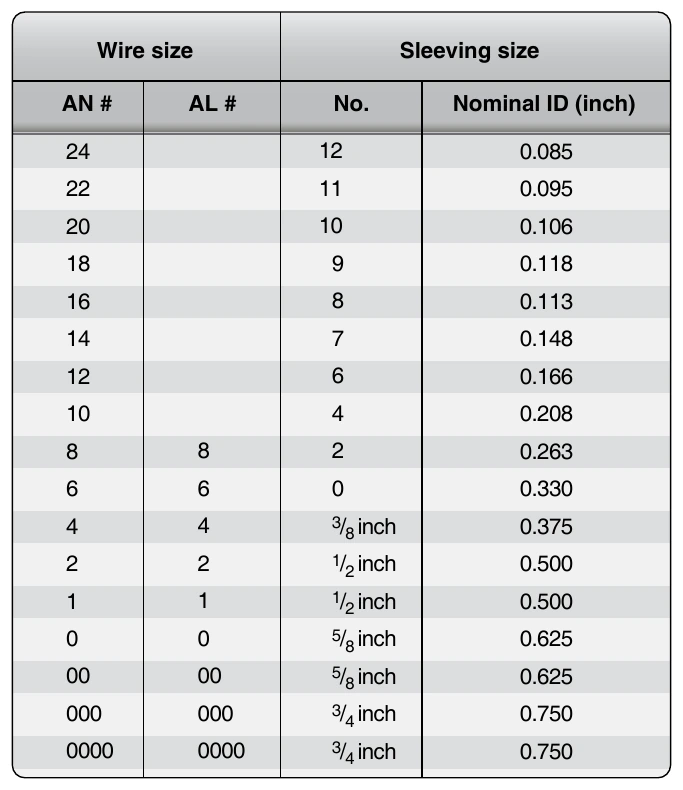
Flexible sleeving, either clear or opaque, is satisfactory for general use. When color-coded or striped component wire is used as part of a cable, the identification sleeve should specify which color is associated with each wire identification code. Identification sleeves are normally used for identifying the following types of wire or cable: unjacketed shielded wire, thermocouple wire, coaxial cable, multiconductor cable, and high temperature wire. In most cases, identification tape can be used in place of sleeving. For sleeving exposed to high temperatures (over 400 °F), materials, such as silicone fiberglass, should be used. Polyolefin sleeving should be used in areas where resistance to solvent and synthetic hydraulic fluids is necessary. Sleeves may be secured in place with cable ties or by heat shrinking. The identification sleeving for various sizes of wire is shown in Figure 9-128.
Wire Installation & Routing
Open Wiring
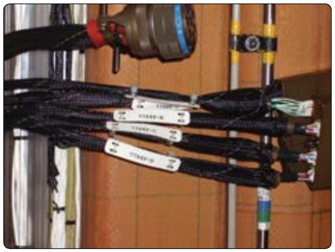
Interconnecting wire is used in point-to-point open harnesses, normally in the interior or pressurized fuselage, with each wire providing enough insulation to resist damage from handling and service exposure. Electrical wiring is often installed in aircraft without special enclosing means. This practice is known as open wiring and offers the advantages of ease of maintenance and reduced weight.
Wire Groups & Bundles & Routing
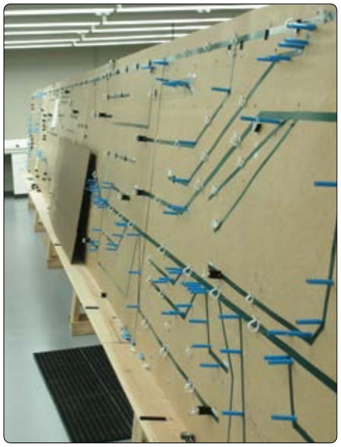
Wires are often installed in bundles to create a more organized installation. These wire bundles are often called wire harnesses. Wire harnesses are often made in the factory or electrical shop on a jig board so that the wire bundles could be preformed to fit into the aircraft. [Figure 9-129] As a result, each harness for a particular aircraft installation is identical in shape and length. The wiring harness could be covered by a shielding (metal braid) to avoid EMI. Grouping or bundling certain wires, such as electrically unprotected power wiring and wiring going to duplicate vital equipment, should be avoided. Wire bundles should generally be less than 75 wires, or 11⁄2 to 2 inches in diameter where practicable. When several wires are grouped at junction boxes, terminal blocks, panels, etc., identity of the groups within a bundle can be retained.
Slack in Wire Bundles
Wiring should be installed with sufficient slack so that bundles and individual wires are not under tension. Wires connected to movable or shock-mounted equipment should have sufficient length to allow full travel without tension on the bundle. Wiring at terminal lugs or connectors should have sufficient slack to allow two reterminations without replacement of wires. This slack should be in addition to the drip loop and the allowance for movable equipment. Normally, wire groups or bundles should not exceed 1⁄2 inch deflection between support points. [Figure 9-130] This measurement may be exceeded if there is no possibility of the wire group or bundle touching a surface that may cause abrasion. Sufficient slack should be provided at each end to permit replacement of terminals and ease of maintenance; prevent mechanical strain on the wires, cables, junctions, and supports; permit free movement of shock- and vibration-mounted equipment; and allow shifting of equipment, as necessary, to perform alignment, servicing, tuning, removal of dust covers, and changing of internal components while installed in aircraft.
Twisting Wires
When specified on the engineering drawing, or when accomplished as a local practice, parallel wires must sometimes be twisted. The following are the most common examples:
- Wiring in the vicinity of magnetic compass or flux valve
- Three-phase distribution wiring
- Certain other wires (usually radio wiring) as specified on engineering drawings