
Chapter 9
Aircraft Electrical System
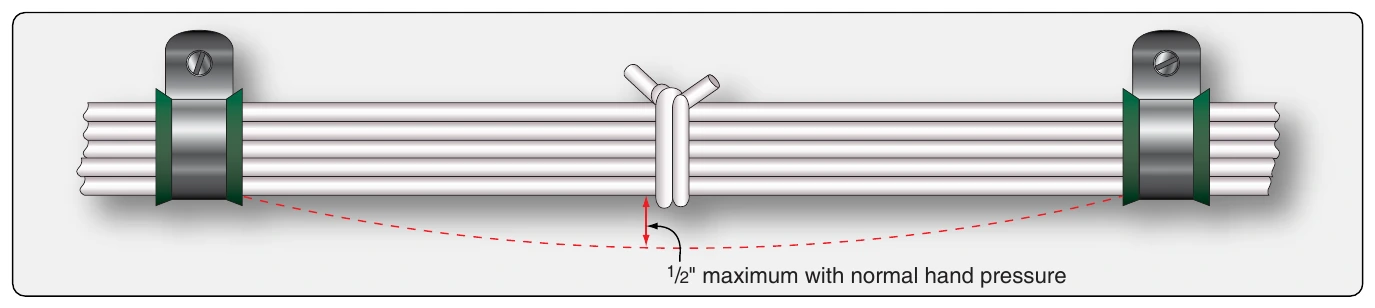
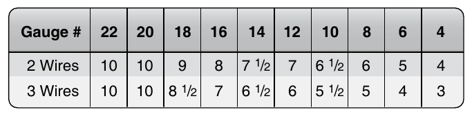
Twist the wires so they lie snugly against each other, making approximately the number of twists per foot as shown in
twisting. If the insulation is torn or frayed, replace the wire.
Spliced Connections in Wire Bundles
Splicing is permitted on wiring as long as it does not affect the reliability and the electromechanical characteristics of the wiring. Splicing of power wires, coaxial cables, multiplex bus, and large-gauge wire must have approved data. Splicing of electrical wire should be kept to a minimum and avoided entirely in locations subject to extreme vibrations. Splicing of individual wires in a group or bundle should have engineering approval, and the splice(s) should be located to allow periodic inspection.
Many types of aircraft splice connector are available for use when splicing individual wires. Use of a self-insulated splice connector is preferred; however, a non-insulated splice connector may be used provided the splice is covered with plastic sleeving that is secured at both ends. Environmentally sealed splices that conform to MIL-T-7928 provide a reliable means of splicing in SWAMP areas. However, a non-insulated splice connector may be used, provided the splice is covered with dual-wall shrink sleeving of a suitable material.
There should be no more than one splice in any one wire segment between any two connectors or other disconnect points. Exceptions include when attaching to the spare pigtail lead of a potted connector, when splicing multiple wires to a single wire, when adjusting wire size to fit connector contact crimp barrel size, and when required to make an approved repair.
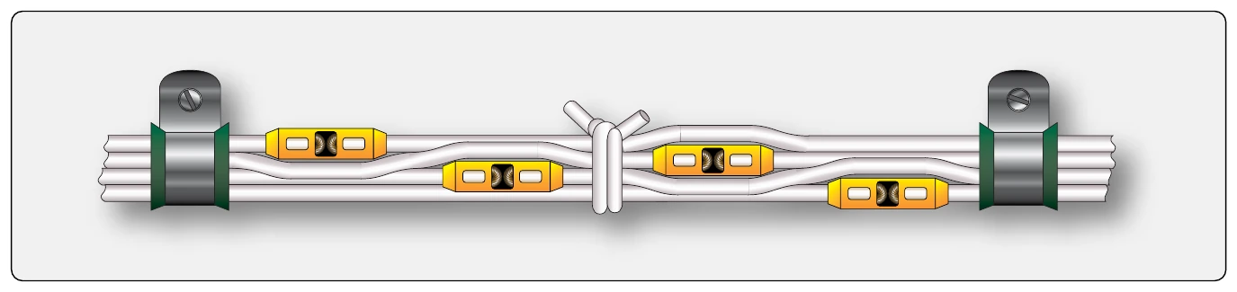
Splices in bundles must be staggered to minimize any increase in the size of the bundle, preventing the bundle from fitting into its designated space or causing congestion that adversely affects maintenance. [Figure 9-132]
Splices should not be used within 12 inches of a termination device, except when attaching to the pigtail spare lead of a potted termination device, to splice multiple wires to a single wire, or to adjust the wire sizes so that they are compatible with the contact crimp barrel sizes.
Bend Radii
T he minimum radius of bends in wire groups or bundles must not be less than 10 times the outside diameter of the largest wire or cable, except that at the terminal strips where wires break out at terminations or reverse direction in a bundle. Where the wire is suitably supported, the radius may be three times the diameter of the wire or cable. Where it is not practical to install wiring or cables within the radius requirements, the bend should be enclosed in insulating tubing. The radius for thermocouple wire should be done in accordance with the manufacturer’s recommendation and shall be sufficient to avoid excess losses or damage to the cable. Ensure that RF cables (e.g., coaxial and triaxial) are bent at a radius of no less than six times the outside diameter of the cable.
Protection Against Chafing
Wires and wire groups should be protected against chafing or abrasion in those locations where contact with sharp surfaces or other wires would damage the insulation, or chafing could occur against the airframe or other components. Damage to the insulation can cause short circuits, malfunction, or inadvertent operation of equipment.
Protection Against High Temperature
Wiring must be routed away from high-temperature equipment and lines to prevent deterioration of insulation. Wires must be rated so the conductor temperature remains within the wire specification maximum when the ambient temperature and heat rise related to current-carrying capacity are taken into account. The residual heating effects caused by exposure to sunlight when aircraft are parked for extended periods should also be taken into account. Wires, such as those used in fire detection, fire extinguishing, fuel shutoff, and fly-by-wire flight control systems that must operate during and after a fire, must be selected from types that are qualified to provide circuit integrity after exposure to fire for a specified period. Wire insulation deteriorates rapidly when subjected to high temperatures.
Separate wires from high-temperature equipment, such as resistors, exhaust stacks, heating ducts, to prevent insulation breakdown. Insulate wires that must run through hot areas with a high-temperature insulation material, such as fiberglass or PTFE. Avoid high-temperature areas when using cables with soft plastic insulation, such as polyethylene, because these materials are subject to deterioration and deformation at elevated temperatures. Many coaxial cables have this type of insulation.
Protection Against Solvents & Fluids
An arcing fault between an electrical wire and a metallic flammable fluid line may puncture the line and result in a fire. Every effort must be made to avoid this hazard by physical separation of the wire from lines and equipment containing oxygen, oil, fuel, hydraulic fluid, or alcohol. Wiring must be routed above these lines and equipment with a minimum separation of 6 inches or more whenever possible. When such an arrangement is not practicable, wiring must be routed so that it does not run parallel to the fluid lines. A minimum of 2 inches must be maintained between wiring and such lines and equipment, except when the wiring is positively clamped to maintain at least 1⁄2-inch separation, or when it must be connected directly to the fluid-carrying equipment. Install clamps as shown in Figure 9-133. These clamps should not be used as a means of supporting the wire bundle. Additional clamps should be installed to support the wire bundle and the clamps fastened to the same structure used to support the fluid line(s) to prevent relative motion.