
Chapter 10
Inspection Concepts & Techniques
Identification of Indications
The correct evaluation of the character of indications is extremely important but is sometimes difficult to make from observation of the indications alone. The principal distinguishing features of indications are shape, buildup, width, and sharpness of outline. These characteristics are more valuable in distinguishing between types of discontinuities than in determining their severity. Careful observation of the character of the magnetic particle pattern must always be included in the complete evaluation of the significance of an indicated discontinuity.
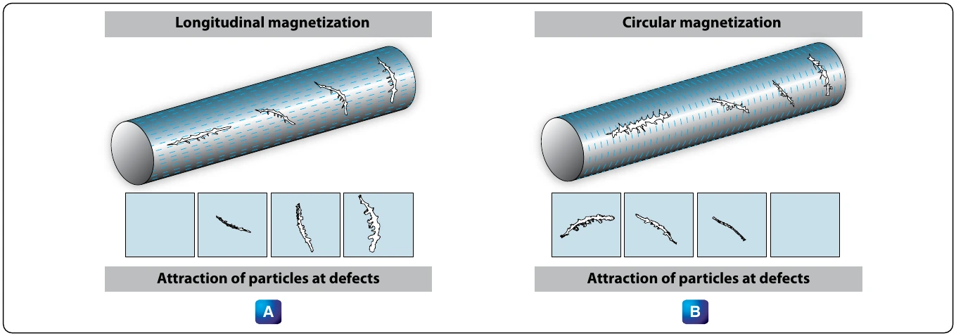
The most readily distinguished indications are those produced by cracks open to the surface. These discontinuities include fatigue cracks, heat-treat cracks, shrink cracks in welds and castings, and grinding cracks. An example of a fatigue crack is shown in Figure 10-31.
Magnaglo Inspection
Magnaglo inspection is similar to the preceding method, but differs in that a fluorescent particle solution is used and the inspection is made under black light. [Figure 10-32] Efficiency of inspection is increased by the neon-like glow of defects allowing smaller flaw indications to be seen. This is an excellent method for use on gears, threaded parts, and aircraft engine components. The reddish-brown liquid spray or bath that is used consists of Magnaglo paste mixed with a light oil at the ratio of 0.10 to 0.25 ounce of paste per gallon of oil. After inspection, the part must be demagnetized and rinsed with a cleaning solvent.
Magnetizing Equipment
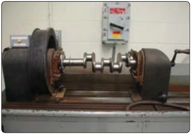
Fixed (Nonportable) General Purpose Unit A fixed, general purpose unit provides direct current (DC) for wet, continuous, or residual magnetization procedures. [Figure 10-33] Circular or longitudinal magnetization may be used, and it may be powered with rectified AC, as well as DC. The contact heads provide the electrical terminals for circular magnetization. One head is fixed in position with its contact plate mounted on a shaft surrounded by a pressure spring so that the plate may be moved longitudinally. The plate is maintained in the extended position by the spring until pressure transmitted through the work from the movable head forces it back.
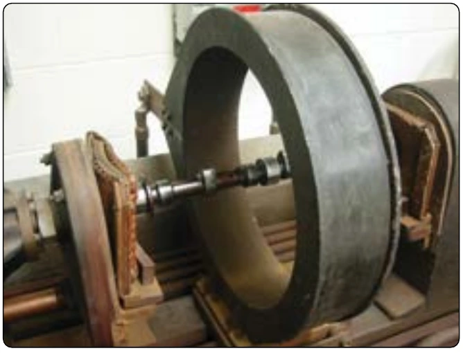
The motor-driven movable head slides horizontally in longitudinal guides and is controlled by a switch. The spring allows sufficient overrun of the motor-driven head to avoid jamming it and also provides pressure on the ends of the work to ensure good electrical contact.
A plunger-operated switch in the fixed head cuts out the forward motion circuit of the movable head motor when the spring has been properly compressed. In some units, the movable head is hand operated, and the contact plate is sometimes arranged for operation by an air ram. Both contact plates are fitted with various fixtures for supporting the work.
The magnetizing circuit is closed by depressing a pushbutton on the front of the unit. It is set to open automatically, usually after about one-half second. The strength of the magnetizing current may be set manually to the desired value by means of the rheostat or increased to the capacity of the unit by the rheostat short circuiting switch. The current utilized is indicated on the ammeter. Longitudinal magnetization is produced by the solenoid that moves in the same guide rail as the movable head and is connected in the electrical circuit by means of a switch.
The suspension liquid is contained in a sump tank and is agitated and circulated by a pump. The suspension is applied to the work through a nozzle. The suspension drains from the work through a nonmetallic grill into a collecting pan that leads back to the sump. The circulating pump is operated by a pushbutton switch.
Portable General Purpose Unit
It is often necessary to perform the magnetic particle inspection at locations where fixed general purpose equipment is not available or to perform an inspection on members of aircraft structures without removing them from the aircraft. It is particularly useful for inspecting landing gear and engine mounts suspected of having developed cracks in service. Portable units supply both AC and DC magnetization.
This unit is a source of magnetizing and demagnetizing current but does not provide a means for supporting the work or applying the suspension. It operates on 200 volt, 60 cycle AC and contains a rectifier for producing DC when required. [Figure 10-34]
The magnetizing current is supplied through the flexible cables with prods or contact clamps, as shown in Figure 10-35. The cable terminals may be fitted with prods or with contact clamps. Circular magnetization may be developed by using either the prods or clamps.
Longitudinal magnetization is developed by wrapping the cable around the part. The strength of the magnetizing current is controlled by an eight-point tap switch, and the duration that it is applied is regulated by an automatic cutoff similar to that used in the fixed general purpose unit.
This portable unit also serves as a demagnetizer and supplies high amperage, low-voltage AC for this purpose. For demagnetization, the AC is passed through the part and gradually reduced by means of a current reducer. In testing large structures with flat surfaces where current must be passed through the part, it is sometimes impossible to use contact clamps. In such cases, contact prods are used.