
Chapter 10
Inspection Concepts & Techniques
Grease, oil, and dirt must be cleaned from all parts before they are tested. Cleaning is very important since any grease or other foreign material present can produce nonrelevant indications due to magnetic particles adhering to the foreign material as the suspension drains from the part.
Grease or foreign material in sufficient amount over a discontinuity may also prevent the formation of a pattern at the discontinuity. It is not advisable to depend upon the magnetic particle suspension to clean the part. Cleaning by suspension is not thorough and any foreign materials so removed from the part contaminates the suspension, thereby reducing its effectiveness.
In the dry procedure, thorough cleaning is absolutely necessary. Grease or other foreign material holds the magnetic powder, resulting in nonrelevant indications and making it impossible to distribute the indicating medium evenly over the part’s surface. All small openings and oil holes leading to internal passages or cavities must be plugged with paraffin or other suitable nonabrasive material.
Coatings of cadmium, copper, tin, and zinc do not interfere with the satisfactory performance of magnetic particle inspection, unless the coatings are unusually heavy or the discontinuities to be detected are unusually small.
Chromium and nickel plating generally do not interfere with indications of cracks open to the surface of the base metal, but prevent indications of fine discontinuities, such as inclusions. Because it is more strongly magnetic, nickel plating is more effective than chromium plating in preventing the formation of indications.
Effect of Flux Direction
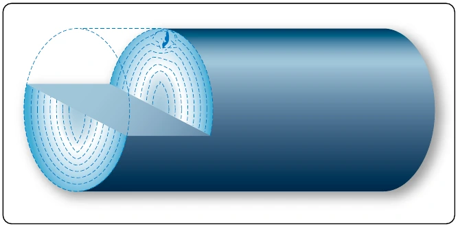
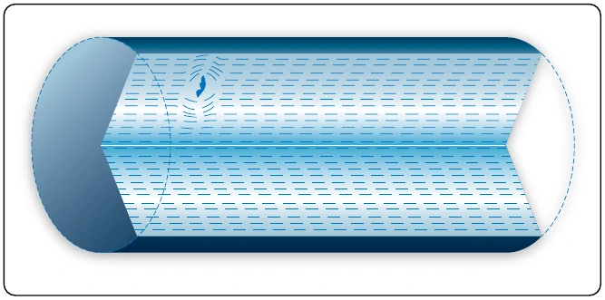
To locate a defect in a part, it is essential that the magnetic lines of force pass approximately perpendicular to the defect. It is, therefore, necessary to induce magnetic flux in more than one direction, since defects are likely to exist at any angle to the major axis of the part. This requires two separate magnetizing operations, referred to as circular magnetization and longitudinal magnetization. The effect of flux direction is illustrated in Figure 10-28.
Circular magnetization is the induction of a magnetic field consisting of concentric circles of force about and within the part. This is achieved by passing electric current through the part, locating defects running approximately parallel to the axis of the part. Figure 10-29 illustrates circular magnetization of a crankshaft. In longitudinal magnetization, the magnetic field is produced in a direction parallel to the long axis of the part. This is accomplished by placing the part in a solenoid excited by electric current. The metal part then becomes the core of an electromagnet and is magnetized by induction from the magnetic field created in the solenoid. In longitudinal magnetization of long parts, the solenoid must be moved along the part in order to magnetize it. [Figure 10-30] This is necessary to ensure adequate field strength throughout the entire length of the part.
Solenoids produce effective magnetization for approximately 12 inches from each end of the coil, thus accommodating parts or sections approximately 30 inches in length. Longitudinal magnetization equivalent to that obtained by a solenoid may be accomplished by wrapping a flexible electrical conductor around the part. Although this method is not as convenient, it has an advantage in that the coils conform more closely to the shape of the part, producing a somewhat more uniform magnetization. The flexible coil method is also useful for large or irregularly-shaped parts when standard solenoids are not available.
Effect of Flux Density
The effectiveness of the magnetic particle inspection also depends on the flux density or field strength at the surface of the part when the indicating medium is applied. As the flux density in the part is increased, the sensitivity of the test increases, because of the greater flux leakages at discontinuities and the resulting improved formation of magnetic particle patterns.
Excessively high flux densities may form nonrelevant indications, such as patterns of the grain flow in the material. These indications interfere with the detection of patterns resulting from significant discontinuities. It is therefore necessary to use a field strength high enough to reveal all possible harmful discontinuities, but not strong enough to produce confusing nonrelevant indications.
Magnetizing Methods
When a part is magnetized, the field strength in the part increases to a maximum for the particular magnetizing force and remains at this maximum as long as the magnetizing force is maintained.
When the magnetizing force is removed, the field strength decreases to a lower residual value depending on the magnetic properties of the material and the shape of the part. These magnetic characteristics determine whether the continuous or residual method is used in magnetizing the part.
In the continuous inspection method, the part is magnetized and the indicating medium applied while the magnetizing force is maintained. The available flux density in the part is thus at a maximum. The maximum value of flux depends directly upon the magnetizing force and the permeability of the material that the part is made of.
The continuous method may be used in practically all circular and longitudinal magnetization procedures. The continuous procedure provides greater sensitivity than the residual procedure, particularly in locating subsurface discontinuities. The highly critical nature of aircraft parts and assemblies and the necessity for subsurface inspection in many applications have resulted in the continuous method being more widely used. Since the continuous procedure reveals more nonsignificant discontinuities than the residual procedure, careful and intelligent interpretation and evaluation of discontinuities revealed by this procedure are necessary.
The residual inspection procedure involves magnetization of the part and application of the indicating medium after the magnetizing force has been removed. This procedure relies on the residual or permanent magnetism in the part and is more practical than the continuous procedure when magnetization is accomplished by flexible coils wrapped around the part. In general, the residual procedure is used only with steels that have been heat-treated for stressed applications.