
Chapter 10
Inspection Concepts & Techniques
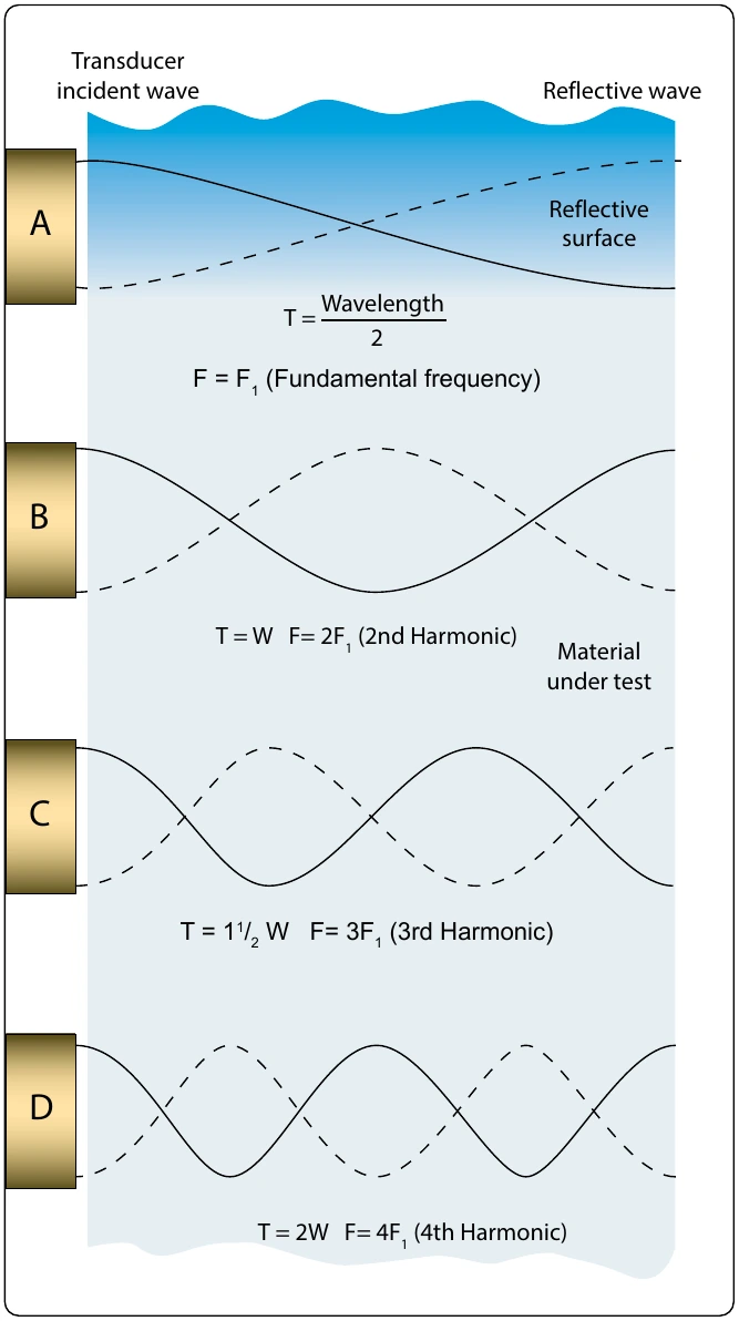
waves corresponding to a particular dial setting be interface. accurately known. Checks should be made with standard te3st. bloTcykpse t oII Ig—uavrdo iadgs abinetswt peoenss liabylee rdsr iofft oaf l afrmeqinuaetnec.y.
- Type IV—voids in foam adhesive or disbonds between
If the frequency of an ultrasonic wave is such that its the adhesive and a closure member at core-to-closure wavelmenegmthb eirs jtowinictse. the thickness of a specimen (funda-mental frequency), then the reflected wave will arrive ba5c. k aTty tphee Vtr—anwsdautecre irn i nth teh ceo sraem. e phase as the original transmission so that strengthening of the signal will
Acoustic Emission Inspection
occur. This results from constructive interference or a Acoustic emission is an NDI technique that involves the resonance and is shown as a high amplitude value on placing of acoustic emission sensors at various locations the indicating screen. If the frequency is increased such on an aircraft structure and then applying a load or stress. that three times the wavelength equals four times the The materials emit sound and stress waves that take the thickness, the reflected signal will return completely form of ultrasonic pulses. Cracks and areas of corrosion in out of phase with the transmitted signal and cancella-the stressed airframe structure emit sound waves that are rteigoins twerielld o bcyc utrh.e F suernthseorr si.n Tcrheeassee aocfo tuhset ifcr eeqmuiesnscioyn c bauurssetss ctahne bwea uvseeledn tgot hlo tcoa tbee f elaqwusa la tnod thtoe ethviaclukantees sth aegira irnat ae nodf ggriovwetsh a a sre afl feucntecdti osnig onfa al pipnl ipehda sstere wssi.t Ah ctohues ttrica nesmmisitstieodn tseisgtinnagl haansd a an raedsvoannatangcee oovnecr eo tmheorr eN.DI methods in that it can detect and locate all of the activated flaws in a structure By starting at the fundamental frequency and gradually in one test. Because of the complexity of aircraft structures, increasing the frequency, the successive cancellations and resonances can be noted and the readings used
Magnetic Particle Inspection
Magnetic particle inspection is a method of detecting invisible cracks and other defects in ferromagnetic materials, such as iron and steel. It is not applicable to nonmagnetic materials. In rapidly rotating, reciprocating, vibrating, and other highly-stressed aircraft parts, small defects often develop to the point that they cause complete failure of the part. Magnetic particle inspection has proven extremely reliable for the rapid detection of such defects located on or near the surface. With this method of inspection, the location of the defect is indicated and the approximate size and shape are outlined.
The inspection process consists of magnetizing the part and then applying ferromagnetic particles to the surface area to be inspected. The ferromagnetic particles (indicating medium) may be held in suspension in a liquid that is flushed over the part; the part may be immersed in the suspension liquid; or the particles, in dry powder form, may be dusted over the surface of the part. The wet process is more commonly used in the inspection of aircraft parts.
If a discontinuity is present, the magnetic lines of force are disturbed and opposite poles exist on either side of the discontinuity. The magnetized particles thus form a pattern in the magnetic field between the opposite poles. This pattern, known as an “indication,” assumes the approximate shape of the surface projection of the discontinuity. A discontinuity may be defined as an interruption in the normal physical structure or configuration of a part, such as a crack, forging lap, seam, inclusion, porosity, and the like. A discontinuity may or may not affect the usefulness of a part.
Development of Indications
When a discontinuity in a magnetized material is open to the surface and a magnetic substance (indicating medium) is available on the surface, the flux leakage at the discontinuity tends to form the indicating medium into a path of higher permeability. (Permeability is a term used to refer to the ease that a magnetic flux can be established in a given magnetic circuit.) Because of the magnetism in the part and the adherence of the magnetic particles to each other, the indication remains on the surface of the part in the form of an approximate outline of the discontinuity that is immediately below it. The same action takes place when the discontinuity is not open to the surface, but since the amount of flux leakage is less, fewer particles are held in place and a fainter and less sharply defined indication is obtained.
If the discontinuity is very far below the surface, there may be no flux leakage and no indication on the surface. The flux leakage at a transverse discontinuity is shown in Figure 10-26. The flux leakage at a longitudinal discontinuity is shown in Figure 10-27.
Types of Discontinuities Disclosed
The following types of discontinuities are normally detected by the magnetic particle test: cracks, laps, seams, cold shuts, inclusions, splits, tears, pipes, and voids. All of these may affect the reliability of parts in service.
Cracks, splits, bursts, tears, seams, voids, and pipes are formed by an actual parting or rupture of the solid metal. Cold shuts and laps are folds that have been formed in the metal, interrupting its continuity.
Inclusions are foreign material formed by impurities in the metal during the metal processing stages. They may consist, for example, of bits of furnace lining picked up during the melting of the basic metal or of other foreign constituents. Inclusions interrupt the continuity of the metal, because they prevent the joining or welding of adjacent faces of the metal.