
Chapter 10
Inspection Concepts & Techniques
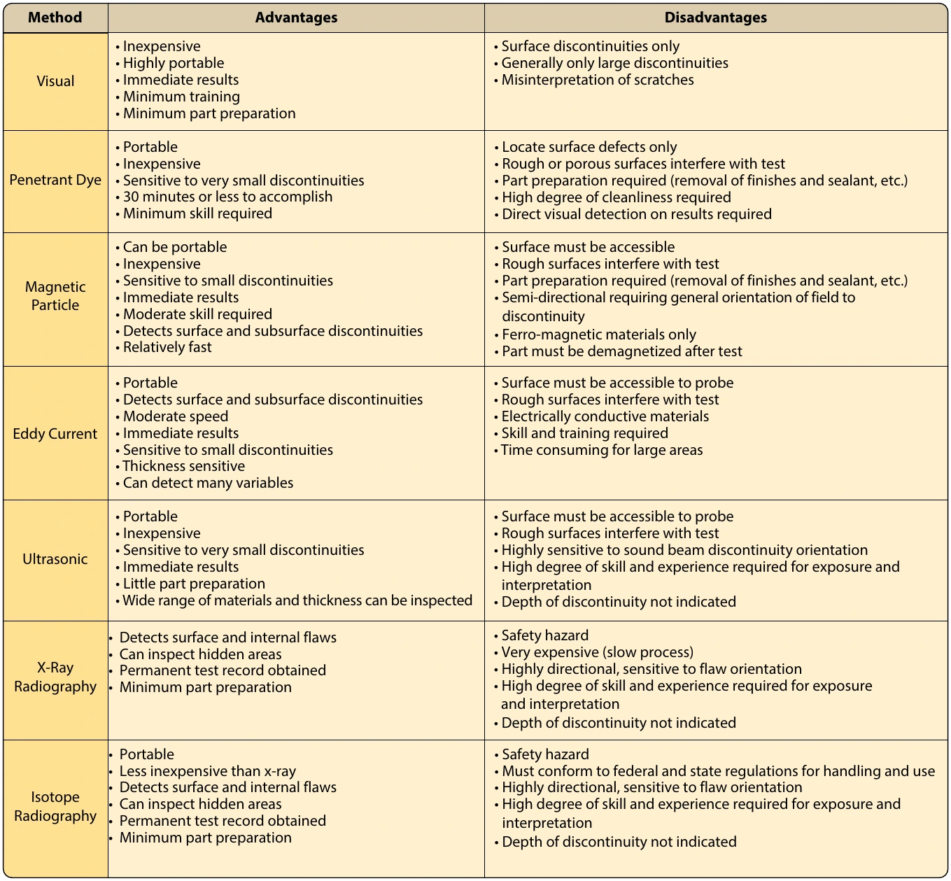
Penetrant inspection detects defects, such as surface cracks or porosity. These defects may be caused by fatigue cracks, shrinkage cracks, shrinkage porosity, cold shuts, grinding and heat-treat cracks, seams, forging laps, and bursts. Penetrant inspection also indicates a lack of bond between joined metals. The main disadvantage of penetrant inspection is that the defect must be open to the surface in order to let the penetrant get into the defect. For this reason, if the part in question is made of material that is magnetic, the use of magnetic particle inspection is generally recommended.
Penetrant inspection uses a penetrating liquid that enters a surface opening and remains there, making it clearly visible to the inspector. It calls for visual examination of the part after it has been processed, increasing the visibility of the defect so that it can be detected. Visibility of the penetrating material is increased by the addition of one or two types of dye: visible or fluorescent.
The visible penetrant kit consists of dye penetrant, dye remover emulsifier, and developer. The fluorescent penetrant inspection kit contains a black light assembly, as well as spray cans of penetrant, cleaner, and developer. The light assembly consists of a power transformer, a flexible power cable, and a hand-held lamp. Due to its size, the lamp may be used in almost any position or location.
The steps for performing a penetrant inspection are:
- Clean the metal surface thoroughly.
- Apply penetrant.
- Remove penetrant with remover emulsifier or cleaner.
- Dry the part.
- Apply the developer.
- Inspect and interpret results.
Interpretation of Results
The success and reliability of a penetrant inspection depends upon the thoroughness that the part was prepared with. Several basic principles applying to penetrant inspection are:
- The penetrant must enter the defect in order to form an indication. It is important to allow sufficient time so the penetrant can fill the defect. The defect must be clean and free of contaminating materials so that the penetrant is free to enter.
- If all penetrant is washed out of a defect, an indication cannot be formed. During the washing or rinsing operation, prior to development, it is possible that the penetrant is removed from within the defect, as well as from the surface.
- Clean cracks are usually easy to detect. Surface openings that are uncontaminated, regardless of how
- The smaller the defect, the longer the penetrating time. Fine crack-like apertures require a longer penetrating time than defects such as pores.
- When the part to be inspected is made of a material susceptible to magnetism, it should be inspected by a magnetic particle inspection method if the equipment is available.
- Visible penetrant-type developer, when applied to the surface of a part, dries to a smooth, white coating. As the developer dries, bright red indications appear where there are surface defects. If no red indications appear, there are no surface defects.
- When conducting the fluorescent penetrant-type inspection, the defects show up (under black light) as a brilliant yellow-green color and the sound areas appear deep blue-violet.
- It is possible to examine an indication of a defect and to determine its cause as well as its extent. Such an appraisal can be made if something is known about the manufacturing processes that the part has been subjected to.
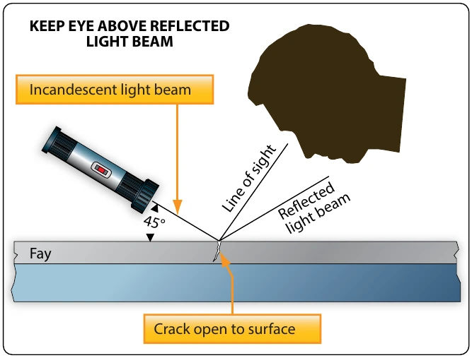
The size of the indication, or accumulation of penetrant, shows the extent of the defect and the brilliance is a measure of its depth. Deep cracks hold more penetrant and are [Figure 10-9]
False Indications
With the penetrant inspection, there are no false indications in the sense that they occur in the magnetic particle inspection. There are, however, two conditions that may create accumulations of penetrant that are sometimes confused with true surface cracks and discontinuities.
The first condition involves indications caused by poor washing. If all the surface penetrant is not removed in the washing or rinsing operation following the penetrant dwell time, the unremoved penetrant is visible. Evidences of incomplete washing are usually easy to identify since the penetrant is in broad areas rather than in the sharp patterns found with true indications. When accumulations of unwashed penetrant are found on a part, the part must be completely reprocessed. Degreasing is recommended for removal of all traces of the penetrant.
False indications may also be created where parts press fit to each other. If a wheel is press fit onto a shaft, penetrant shows an indication at the fit line. This is perfectly normal since the two parts are not meant to be welded together. Indications of this type are easy to identify since they are regular in form and shape.
Eddy Current Inspection
Electromagnetic analysis is a term describing the broad spectrum of electronic test methods involving the intersection of magnetic fields and circulatory currents. The most widely used technique is the eddy current. Eddy currents are composed of free electrons under the influence of an induced electromagnetic field that are made to “drift” through metal.
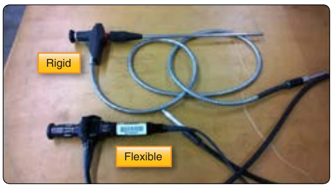
Eddy current is used in aircraft maintenance to inspect jet engine turbine shafts and vanes, wing skins, wheels, bolt holes, and spark plug bores for cracks, heat, or frame damage. Eddy current may also be used in repair of aluminum aircraft damaged by fire or excessive heat. Different meter readings are seen when the same metal is in different hardness states. Readings in the affected area are compared with identical materials in known unaffected areas for comparison. A difference in readings indicates a difference in the hardness state of the affected area. In aircraft manufacturing plants, eddy current is used to inspect castings, stampings, machine parts, forgings, and extrusions. Figure 10-10 shows a technician performing an eddy current inspection on a fan blade.