
Chapter 10
Inspection Concepts & Techniques
Basic Principles
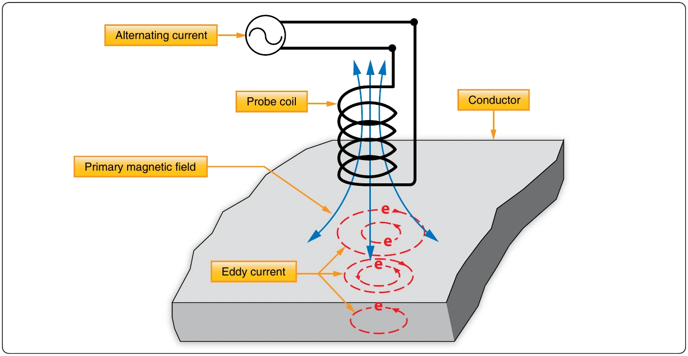
When an alternating current (AC) is passed through a coil, it develops a magnetic field around the coil, which in turn induces a voltage of opposite polarity in the coil and opposes the flow of original current. If this coil is placed in such a way that the magnetic field passes through an electrically conducting specimen, eddy currents are induced into the specimen. The eddy currents create their own field that varies the original field’s opposition to the flow of original current. The specimen’s susceptibility to eddy currents determines the current flow through the coil.
The magnitude and phase of this counter field is dependent primarily upon the resistance and permeability of the specimen under consideration and enables us to make a qualitative determination of various physical properties of the test material. The interaction of the eddy current field with the original field results is a power change that can be measured by utilizing electronic circuitry similar to a Wheatstone bridge.
applied to a test coil (probe). The AC in the coil induces an alternating magnetic field in the article, causing eddy currents to flow in the article. [Figure 10-11]
Flaws in or thickness changes of the test-piece influence the flow of eddy currents and change the impedance of the coil accordingly. [Figure 10-12] Instruments display the impedance changes either by impedance plane plots or by needle deflection. [Figure 10-13]
The specimen is either placed in or passed through the field of an electromagnetic induction coil, and its effect on the impedance of the coil or on the voltage output of one or more test coils is observed. The process that involves electric fields made to explore a test piece for various conditions involves the transmission of energy through the specimen much like the transmission of x-rays, heat, or ultrasound.
Eddy current inspection can frequently be performed without removing the surface coatings, such as primer, paint, and anodized films. It can be effective in detecting surface and subsurface corrosion, pots, and heat-treat condition.
Eddy Current Instruments
A wide variety of eddy current test instruments are available. The eddy current test instrument performs three basic functions: generating, receiving, and displaying. The generating portion of the unit provides an alternating current to the test coil. The receiving section processes the signal from the test coil to the required form and amplitude for display. Instrument outputs or displays consist of a variety of visual, audible, storage, or transfer techniques utilizing meters, video displays, chart recorders, alarms, magnetic tape, computers, and electrical or electronic relays.
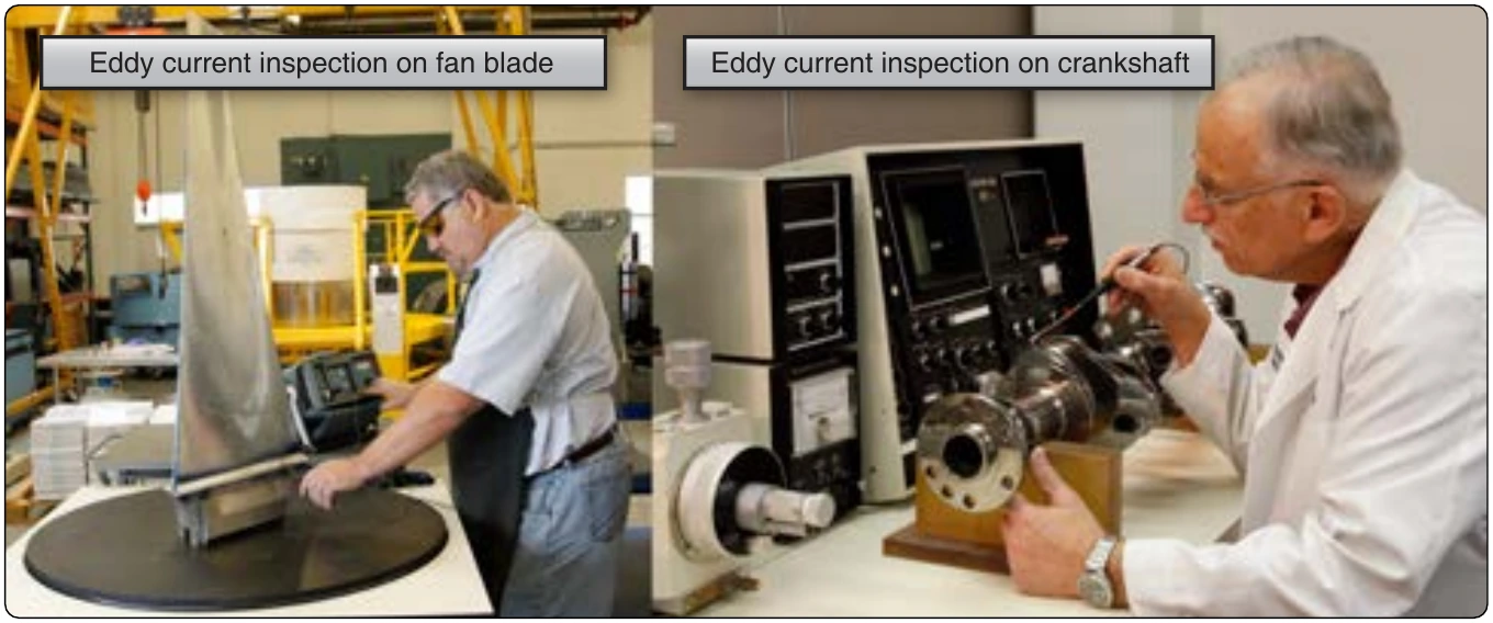
A reference standard is required for the calibration of eddy current test equipment. A reference standard is made from the same material as the item is to be tested. A reference standard contains known flaws or cracks and could include items, such as a flat surface notch, a fastener head, a fastener hole, or a countersink hole. Figures 10-14, 10-15, and 10-16 show typical surface cracks, subsurface cracks, and structural corrosion that can be detected with eddy current techniques.
Ultrasonic Inspection
Ultrasonic inspection is an NDI technique that uses sound energy moving through the test specimen to detect flaws. The sound energy passing through the specimen is displayed on a cathode ray tube (CRT), a liquid crystal display (LCD) computer data program, or video/camera medium. Indications of the front and back surface and internal/external conditions appear as vertical signals on the CRT screen or nodes of data in the computer test program. [Figure 10-17] There are three types of display patterns: “A” scan, “B” scan, and “C” scan. Each scan provides a different picture or view of the specimen being tested. [Figure 10-18]
Ultrasonic detection equipment makes it possible to locate defects in all types of materials. Minute cracks, checks, and voids too small to be seen by x-ray can be located by ultrasonic inspection. An ultrasonic test instrument requires access to only one surface of the material to be inspected and can be used with either straight line or angle beam testing techniques.
Two basic methods are used for ultrasonic inspection. The first of these methods is immersion testing. In this method of inspection, the part under examination and the search unit are completely immersed in a liquid couplant, such as water or other suitable fluids.
The second method is called contact testing. It is readily adapted to field use and is the method discussed in this chapter. In this method, the part under examination and the search unit are coupled with a viscous material, liquid, or a paste that wets both the face of the search unit and the material under examination.
transmission and pulse echo are shown in Figure 10-19.