
Chapter 10
Inspection Concepts & Techniques
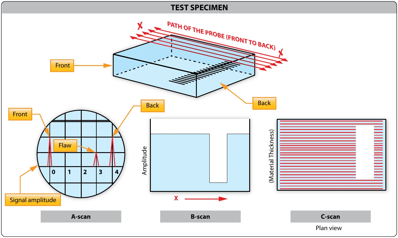
Flaws are detected by measuring the amplitude of signals reflected and the time required for these signals to travel between specific surfaces and the discontinuity. [Figure 10-20]
The time base, triggered simultaneously with each transmission pulse, causes a spot to sweep across the screen of the CRT or LCD. The spot sweeps from left to right across the face of the scope 50 to 5,000 times per second or higher if required for high-speed automated scanning. Due to the speed of the cycle of transmitting and receiving, the picture on the oscilloscope appears to be stationary.
A few microseconds after the sweep is initiated, the rate generator electrically excites the pulser, and the pulser in turn emits an electrical pulse. The transducer converts this pulse into a short train of ultrasonic sound waves. If the interfaces the internal flaw and the opposite surface of the specimen. The time interval between the transmission of the initial impulse and the reception of the signals from within the specimen are measured by the timing circuits. The reflected pulse received by the transducer is amplified, transmitted to, and displayed on the instrument screen. The pulse is displayed in the same relationship to the front and back pulses as the flaw is in relation to the front and back surfaces of the specimen. [Figure 10-21]
Pulse-echo instruments may also be used to detect flaws not directly underneath the probe by use of the angle beam testing method. Angle beam testing differs from straight beam testing only in the manner that the ultrasonic waves pass through the material being tested. As shown in Figure 10-22, the beam is projected into the material at an acute angle to the surface by means of a crystal cut at an angle and mounted in plastic. The beam, or a portion thereof, reflects successively from the surfaces of the material or any other discontinuity, including the edge of the piece. In straight beam testing, the horizontal distance on the screen between the initial pulse and the first back reflection represents the thickness of the piece; while in angle beam testing, this distance represents the width of the material between the searching unit and the opposite edge of the piece.
Through-Transmission
Through-transmission inspection uses two transducers, one to generate the pulse and another placed on the opposite surface
Resonance
This system differs from the pulse method in that the frequency of transmission may be continuously varied. The resonance method is used principally for thickness the material being tested is the thickness determining factor. It is necessary that the frequency of the ultrasonic waves corresponding to a particular dial setting be accurately known. Checks are made with standard test blocks to guard against possible drift of frequency.
If the frequency of an ultrasonic wave is such that its wavelength is twice the thickness of a specimen (fundamental frequency), then the reflected wave arrives back at the transducer in the same phase as the original transmission so that strengthening of the signal occurs. This results from constructive interference or a resonance and is shown as a high amplitude value on the indicating screen. If the frequency is increased such that three times the wavelength equals four times the thickness, the reflected signal returns completely out of phase with the transmitted signal and cancellation occurs. Further increase of the frequency causes the wavelength to be equal to the thickness again and gives a reflected signal in phase with the transmitted signal and a resonance once more. By starting at the fundamental frequency and gradually increasing the frequency, the successive cancellations and resonances can be noted and the readings used to check the fundamental frequency reading. [Figure 10-23]
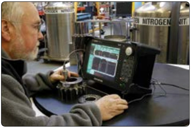
In some instruments, the oscillator circuit contains a motor-driven capacitor that changes the frequency of the oscillator. [Figure 10-24] In other instruments, the frequency is changed by electronic means. The change in frequency is synchronized with the horizontal sweep of a CRT. The horizontal axis represents a frequency range. If the frequency range contains resonances, the circuitry is arranged to present these vertically. Calibrated transparent scales are then placed in front of the tube and the thickness can be read directly. The instruments normally operate between 0.25 millicycle (mc) and 10 mc in four or five bands.
The resonance thickness instrument can be used to test the thickness of such metals as steel, cast iron, brass, nickel, copper, silver, lead, aluminum, and magnesium. In addition, areas of corrosion or wear on tanks, tubing, airplane wing skins,
skilled operator who is familiar with the equipment being used, as well as the inspection method to be used for the many different parts being tested. [Figure 10-25]