
Chapter 12
Fundamentals of Electricity & Electronics
relay cut-out but also serves as a remote control switch by which the generator can be disconnected from the electrical system at any time. One type of reverse current relay switch operates on the voltage level of the generator, but the type most commonly used on large aircraft is the differential relay switch, which is controlled by the difference in voltage the main bus bar in the electrical system when the generator voltage output exceeds the bus voltage by 0.35 to 0.65 volt. It disconnects the generator when a nominal reverse current flows from the bus to the generator. The differential relays on all the generators of a multiengine aircraft do not close when the electrical load is light. For example, in an aircraft having a load of 50 amperes, only two or three relays may close. If a heavy load is applied, the equalizing circuit lowers the voltage of the generators already on the bus and, at the same time, raise the voltage of the remaining generators, allowing their relays to close. If the generators have been paralleled properly, all the relays stay closed until the generator control switch is turned off or until the engine speed falls below the minimum needed to maintain generator output voltage.
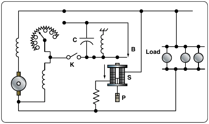
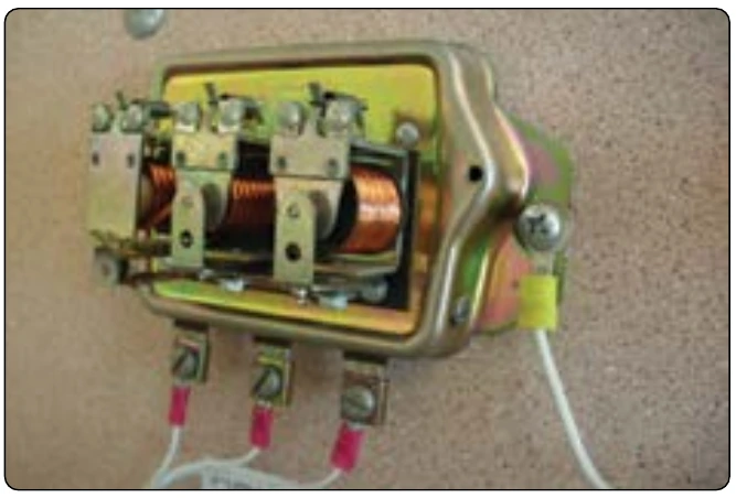
The differential generator control relay shown in Figure 12-331 is made up of two relays and a coil-operated contactor. One relay is the voltage relay and the other is the differential relay. Both relays include permanent magnets that pivot between the pole pieces of temporary magnets wound with relay coils. Voltages of one polarity set up fields about the temporary magnets with polarities that cause the permanent magnet to move in the direction necessary to close the relay contacts; voltages of the opposite polarity establish fields that cause the relay contacts to open. The differential relay has two coils wound on the same core. The coil-operated contactor, called the main contactor, consists of movable contacts that are operated by a coil with a movable iron core.
Closing the generator switch on the control panel connects the generator output to the voltage relay coil. When generator voltage reaches 22 volts, current flows through the coil and closes the contacts of the voltage relay. This action completes a circuit from the generator to the battery through the differential coil.
contractor coil circuit. The contacts of the main contactor close and connect the generator to the bus.
When the generator voltage drops below the bus (or battery) voltage, a reverse current weakens the magnetic field about the temporary magnet of the differential relay. The weakened field permits a spring to open the differential relay contacts, breaking the circuit to the coil of the main contactor relay, opening its contacts, and disconnecting the generator from the bus. The generator battery circuit may also be broken by opening the flight deck control switch, which opens the contacts of the voltage relay, causing the differential relay coil to be de-energized.
Overvoltage & Field Control Relays
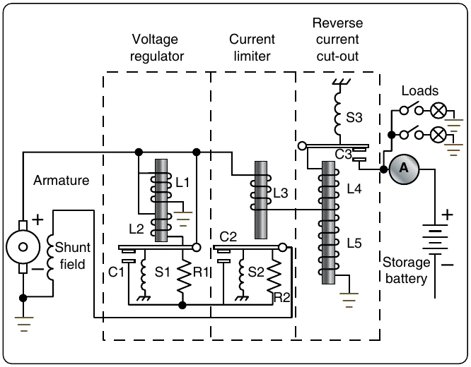
Two other items used with generator control circuits are the overvoltage control and the field control relay. As its name implies, the overvoltage control protects the system when excessive voltage exists. The overvoltage relay is closed when the generator output reaches 32 volts and completes a circuit to the trip coil of the field control relay. The closing of the field control relay trip circuit opens the shunt field circuit and completes it through a resistor, causing generator voltage to drop; also, the generator switch circuit and the equalizer circuit (multiengine aircraft) are opened. An indicator light circuit is completed, warning that an overvoltage condition exists. A “reset” position of the flight deck switch is used to complete a reset coil circuit in the field control relay, returning the relay to its normal position.
Generator Control Units (GCU)
Basic Functions of a Generator Control Unit (GCU)
The generator control unit (GCU) is more commonly found on turbine power aircraft. The most basic GCU perform a number of functions related to the regulation, sensing, and protection of the DC generation system. [Figure 12-332]
Voltage Regulation
The most basic of the GCU functions is that of voltage regulation. Regulation of any kind requires the regulation unit to take a sample of an output and to compare that sample with a controlled reference. If the sample taken falls outside of the limits set by the reference, then the regulation unit must provide an adjustment to the unit generating the output so as to diminish or increase the output levels. In the case of the GCU, the output voltage from a generator is sensed by the GCU and compared to a reference voltage. If there is any difference between the two, the error is usually amplified and then sent back to the field excitation control portion of the circuit. The field excitation control then makes voltage⁄excitation adjustments in the field winding of the generator in order to bring the output voltage back into required bus tolerances.
Overvoltage Protection
Like the voltage regulation feature of the GCU, the overvoltage protection system compares the sampled voltage to reference voltage. The output of the overvoltage protection circuit is used to open the relay that controls the output for the field excitation. These types of faults can occur for a number of reasons. The most common, however, is the failure of the voltage regulation circuit in the GCU.
Parallel Generator Operations
The paralleling feature of the GCU allows for two or more GCU/generator systems to work in a shared effort to provide current to the aircraft electrical system. Comparing voltages between the equalizer bus and the interpole/compensator voltage, and amplifying the differences accomplishes the control of this system. The difference is then sent to the voltage regulation circuit, where adjustments are then made in the regulation output. These adjustments continue until all of the busses are equalized in their load sharing.