
Chapter 12
Fundamentals of Electricity & Electronics
A 12-pole, 4,000 rpm alternator has a frequency of:
Starter Generator
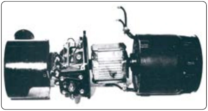
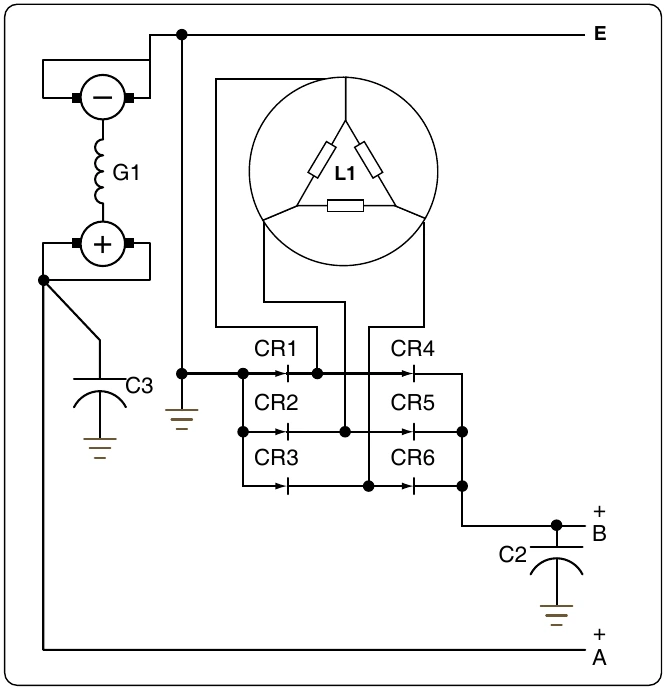
Many turbine-powered aircraft use a starter generator that acts like a starter during the start of the engine and when the engine is online it acts like a Generator. [Figure 12-325] The main advantage of the starter generator is saving weight by eliminating a separate starter that is only used during the start. Initially used on small turboprops and light jets but large units are now installed on the B787 aircraft engines to power the main engines and power the electrical system.
Alternator Rating
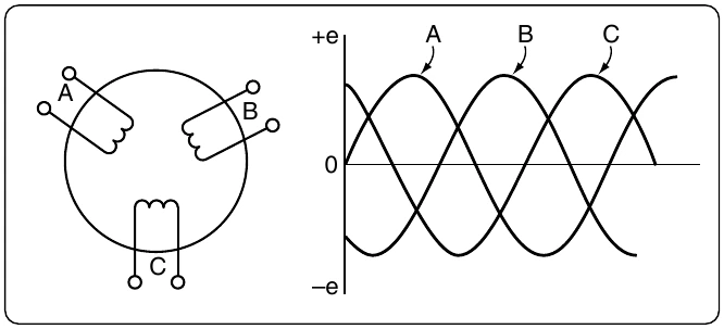
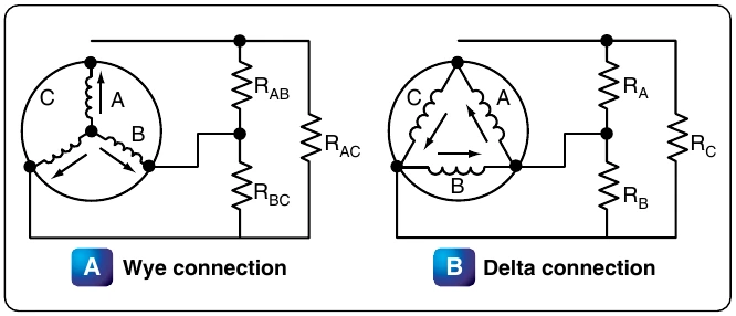
The maximum current that can be supplied by an alternator depends upon the maximum heating loss (I2R power loss) that can be sustained in the armature and the maximum heating loss that can be sustained in the field. The armature current of an alternator varies with the load. This action is similar to that of A 12 pole, 4,000 rpm alternator has a frequency of DC generators. In AC generators, however, lagging power factor loads tend to demagnetize the field of an alternator, and terminal voltage is maintained only by increasing DC field current. For this reason, AC generators are usually rated according to kVA, power factor, phases, voltage, and frequency. One generator, for example, may be rated at 40 kVA, 208 volts, 400 cycles, three phase, at 75 percent power factor. The kVA indicates the apparent power. This is the kVA output, or the relationship between the current and voltage at which the generator is intended to operate. The power factor is the expression of the ratio between the apparent power (volt-amperes) and the true or effective power (watts). The number of phases is the number of independent voltages generated. Three-phase generators generate three voltages 120 electrical degrees apart.
Alternator Maintenance
Maintenance and inspection of alternator systems is similar to that of DC systems. Check the exciter brushes for wear and surfacing. On most large aircraft with two or four alternator systems, each power panel has three signal lights, one connected to each phase of the power bus, so the lamp lights when the panel power is on. The individual buses throughout the airplane can be checked by operating equipment from that particular bus. Consult the manufacturer’s instructions on operation of equipment for the method of testing each bus.
Alternator test stands are used for testing alternators and constant speed drives in a repair facility. They are capable of supplying power to constant speed drive units at input speeds varying from 2,400 rpm to 9,000 rpm.
A typical test stand motor uses 220/440 volt, 60 cycle, three-phase power. Blowers for ventilation, oil coolers, and necessary meters and switches are integral parts of the test stand. A load bank supplies test circuits. An AC motor generator set for ground testing is shown in Figure 12-326.
A typical, portable, AC electrical system test set is an analyzer, consisting of a multirange ohmmeter, a multirange combination AC DC voltmeter, an ammeter with a clip-on current transformer, a vibrating reed type frequency meter, and an unmounted continuity light.
A portable load bank unit furnishes a load similar to that on the airplane for testing alternators, either while mounted in the airplane or on the shop test stand. A complete unit consists of resistive and reactive loads controlled by selector switches and test meters mounted on a control panel. This load unit is compact and convenient, eliminating the difficulty of operating large loads on the airplane while testing and adjusting the alternators and control equipment.
Proper maintenance of an alternator requires that the unit be kept clean and that all electrical connections are tight and in good repair. If the alternator fails to build up voltage as designated by applicable manufacturer’s technical instructions, test the voltmeter first by checking the voltages of other alternators, or by checking the voltage in the suspected alternator with another voltmeter and comparing the results. If the voltmeter is satisfactory, check the wiring, the brushes, and the drive unit for faults. If this inspection fails to reveal the trouble, the exciter may have lost its residual magnetism. Residual magnetism is restored to the exciter by flashing the field. Follow the applicable manufacturer’s instructions when flashing the exciter field. If, after flashing the field, no voltage is indicated, replace the alternator, since it is probably faulty.
Clean the alternator exterior with an approved fluid; smooth a rough or pitted exciter commutator or slip ring with 000 sandpaper; then clean and polish with a clean, dry cloth. Check the brushes periodically for length and general condition. Consult the applicable manufacturer’s instructions on the specific alternator to obtain information on the correct brushes.
Regulation of Generator Voltage
Efficient operation of electrical equipment in an airplane depends on a constant voltage supply from the generator. Among the factors, which determine the voltage output of a generator, only one, the strength of the field current, can be conveniently controlled. To illustrate this control, refer to the diagram in Figure 12-327, showing a simple generator with a rheostat in the field circuit. If the rheostat is set to increase the resistance in the field circuit, less current flows through the field winding and the strength of the magnetic field in which the armature rotates decreases. Consequently, the voltage output of the generator decreases. If the resistance in the field circuit is decreased with the rheostat, more current flows through the field windings, the magnetic field becomes stronger, and the generator produces a greater voltage.