Chapter 12
Fundamentals of Electricity & Electronics
- The resistance of a metallic conductor is dependent on the type of conductor material. It has been pointed out that certain metals are commonly used as conductors because of the large number of free electrons in their outer orbits. Copper is usually considered the best available conductor material, since a copper wire of a particular diameter offers a lower resistance to current flow than an aluminum wire of the same diameter. However, aluminum is much lighter than copper, and for this reason, as well as cost considerations, aluminum is often used when the weight factor is important.
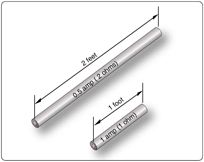
- The resistance of a metallic conductor is directly proportional to its length. The longer the length of a given size of wire, the greater the resistance. Figure 12-41 shows two wire conductors of different lengths. If 1 volt of electrical pressure is applied across
is assumed to be 1 ohm, the current flow is limited to 1 ampere. If the same size conductor is doubled in length, the same electrons set in motion by the 1 volt applied now find twice the resistance; consequently, the current flow is reduced by one-half.
- The resistance of a metallic conductor is inversely proportional to the cross-sectional area. This area may be triangular or even square, but is usually circular. If the cross-sectional area of a conductor is doubled, the resistance to current flow is reduced in half. This is true because of the increased area in which an electron can move without collision or capture by an atom. Thus, the resistance varies inversely with the cross-sectional area of a conductor.
- The fourth major factor influencing the resistance of a conductor is temperature. Although some substances, such as carbon, show a decrease in resistance as the ambient (surrounding) temperature increases, most materials used as conductors increase in resistance as temperature increases. The resistance of a few alloys, such as constantan and Manganin™, change very little as the temperature changes. The amount of increase in the resistance of a 1 ohm sample of a conductor, per degree rise in temperature above 0° Centigrade (C), the assumed standard, is called the temperature coefficient of resistance. For each metal, this is a different value. For example, for copper the value is approximately
degree rise in temperature above 0 °C. The temperature coefficient of resistance must be considered where there is an appreciable change in temperature of a conductor during operation. Charts listing the temperature coefficient of resistance for different materials are available. Figure 12-42 shows a table for “resistivity” of some common electric conductors.
The resistance of a material is determined by four properties: material, length, area, and temperature. The first three
Resistance and Relation to Wire Sizing
Circular Conductors (Wires/Cables)
Because it is known that the resistance of a conductor is directly proportional to its length, and if we are given the resistance of the unit length of wire, we can readily calculate the resistance of any length of wire of that particular material having the same diameter. Also, because it is known that the resistance of a conductor is inversely proportional to its cross-sectional area, and if we are given the resistance of a length of wire with unit cross-sectional area, we can calculate the resistance of a similar length of wire of the same material with any cross-sectional area. Therefore, if we know the resistance of a given conductor, we can calculate the resistance for any conductor of the same material at the same temperature. From the relationship:
It can also be written:
0.017 ohm, what is the resistance of 50 m of wire from the same material but with a cross-sectional area of 0.25 mm2?
While the SI units are commonly used in the analysis of electric circuits, electrical conductors in North America are still being manufactured using the foot as the unit length and the mil (one thousandth of an inch) as the unit of diameter.