
Chapter 12
Fundamentals of Electricity & Electronics
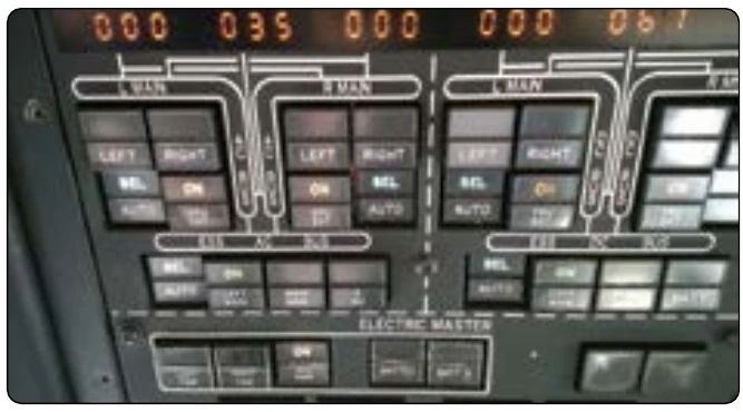
Another more common switch found in today’s aircraft is the lighted pushbutton switch. This type of switch takes the form of a 5⁄8-inch to 1-inch cube with incandescent or LED lights to indicate the function of the switch. Switch designs come in a number of configurations; the two most common are the alternate action and momentary action and usually have a two-pole or four-pole switch body. Other less common body that is energized through two contacts in the base of the switch. When the coil is energized and the switch is pressed, the switch contacts remain latched until power is removed from the coil. This type of design allows for some degree of remote control over the switch body. [Figure 12-78]
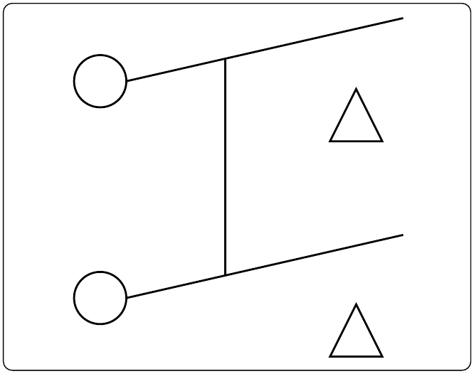
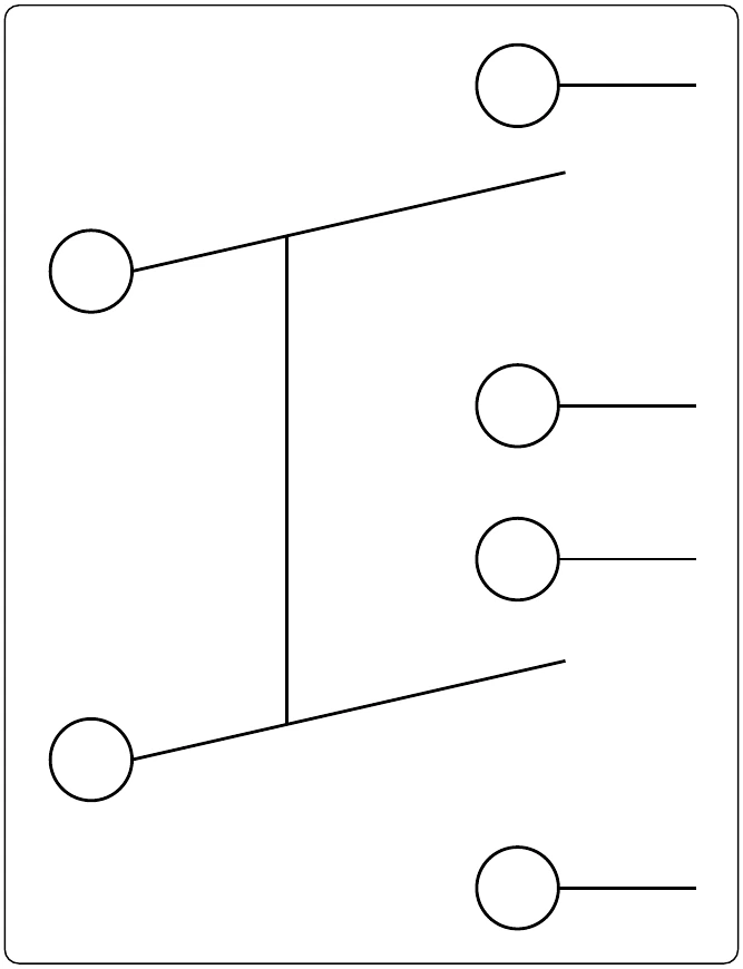
The display optics of the lighted pushbutton switch provide the crew with a clear message that is visible under a wide range of lighting conditions with very high luminance and wide viewing angles. While some displays are simply a transparent screen that is backlit by an incandescent light, the higher quality and more reliable switches are available in sunlight readable displays and night vision (NVIS) versions. Due to the sunlight environment of the flight deck, displays utilizing standard lighting techniques “washout” when viewed in direct sunlight. Sunlight readable displays are designed to minimize this effect.
Lighted pushbutton switches can also be used in applications where a switch is not required and the optics are only for indications. This type of an indicator is commonly called an annunciator.
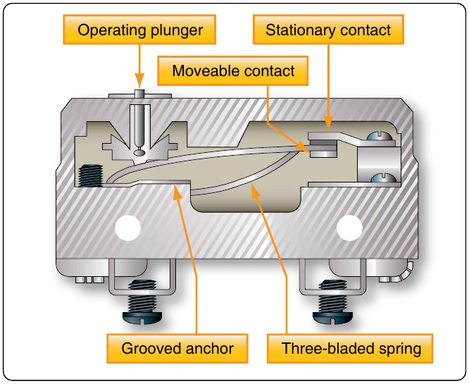
switch in reference to the physical layout. DIP switches are commonly found in card cages, and line replaceable units (LRU) and are used in most cases to adjust gains, control configurations, and so forth. Each one of the switches is generally an SPST slide or rocker switch. The technician may find this switch in packages ranging in size from DIP2 through DIP32. Some of the more common sizes are DIP4 and DIP8.
Switch Guards
Switch guards are covers that protect a switch from unintended operation. Prior to the operation of the switch, the guard is usually lifted. Switch guards are commonly found on systems such as fire suppression and override logics for various systems. Figure 12-79A shows a traditional switch with a guard while Figure 12-79B shows a pushbutton switch with a guard. The guard needs to be moved before the switch can be pushed.
Relays
A relay is simply an electromechanical switch where a small amount of current can control a large amount of current. [Figure 12-80] When a voltage is applied to the coil of the down, the circuit between the arm and the normally closed (NC) contacts is opened and the circuit between the arm and the normally open (NO) contacts are closed. When the energizing voltage is removed, the spring returns the arm contacts back to the normally closed (NC) contacts. The relay usually has two connections for the coil. The (+) side is designated as X1 and the ground-side of the coil is designated as X2.
Series DC Circuits
The series circuit is the most basic electrical circuit and provides a good introduction to basic circuit analysis. The series circuit represents the first building block for all of the circuits to be studied and analyzed. Figure 12-81 shows this simple circuit with nothing more than a voltage source or battery, a conductor, and a resistor. This is classified as a series circuit because the components are connected end-to-end, so that the same current flows through each component equally. There is only one path for the current to take and the battery and resistor are in series with each other. Next is to make a few additions to the simple circuit in Figure 12-81.
Figure 12-82 shows an additional resistor and a little more
configuration, the total resistance of the circuit is equal to the sum of the individual resistors. The basic formula is: