
Chapter 12
Fundamentals of Electricity & Electronics
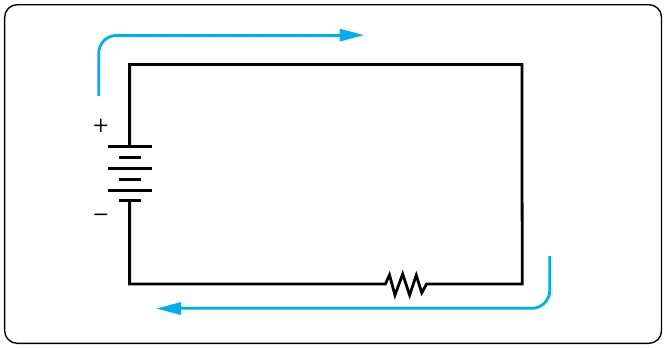
For Figure 12-82, this will be:
Now that the total resistance of the circuit is known, the current for the circuit can be determined. In a series circuit, the current cannot be different at different points within the circuit. The current through a series circuit is always the same through each element and at any point. Therefore, the current in the simple circuit can now be determined using Ohm’s Law:
Ohm’s Law describes a relationship between the variables of voltage, current, and resistance that is linear and easy to illustrate with a few extra calculations. First is the act of changing the total resistance of the circuit while the other two remain constant. In this example, the RT of the circuit in Figure 12-82 is doubled.
The effects on the total current in the circuit are:
It can be seen quantitatively and intuitively that when the resistance of the circuit is doubled, the current is reduced by half the original value.
Next, reduce the RT of the circuit in Figure 12-82 to half of its original value. The effects on the total current are:
Voltage Drops & Further Application of Ohm’s Law
The example circuit in Figure 12-83 is used to illustrate the idea of voltage drop. It is important to differentiate between voltage and voltage drop when discussing series circuits. Voltage drop refers to the loss in electrical pressure or emf caused by forcing electrons through a resistor. Because there are two resistors in the example, there are separate voltage drops. Each drop is associated with each individual resistor. The amount of electrical pressure required to force a given number of electrons through a resistance is proportional to the size of the resistor.
In Figure 12-83, the values used to illustrate the idea of voltage drop are:
The voltage drop across each resistor is calculated using Ohm’s Law. The drop for each resistor is the product of each resistance and the total current in the circuit. Keep in mind that the same current flows through series resistor.
The source voltage can now be determined, which can then be used to confirm the calculations for each voltage drop. Using Ohm’s Law: