
Chapter 12
Fundamentals of Electricity & Electronics
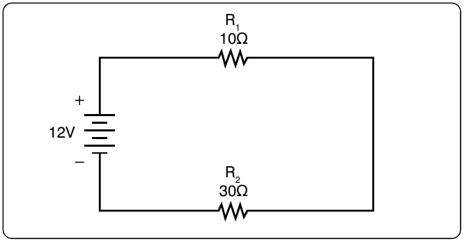
Simple checks to confirm the calculation and to illustrate the concept of the voltage drop add up the individual values of the voltage drops and compare them to the results of the above calculation.
Voltage Sources in Series
A voltage source is an energy source that provides a constant voltage to a load. Two or more of these sources in series equals the algebraic sum of all the sources connected in series. The significance of pointing out the algebraic sum is to indicate that the polarity of the sources must be considered when adding up the sources. The polarity is indicated by a plus or minus sign depending on the source’s position in the circuit.
In Figure 12-84, all of the sources are in the same direction in terms of their polarity. All of the voltages have the same sign when added up. In the case of Figure 12-84, three cells of a value of 1.5 volts are in series with the polarity in the same direction. The addition is simple enough:
However, in Figure 12-85, one of the three sources has been turned around, and the polarity opposes the other two sources. Again the addition is simple:
Kirchhoff’s Voltage Law
A law of basic importance to the analysis of an electrical circuit is Kirchhoff’s Voltage Law. This law simply states that the algebraic sum of all voltages around a closed path or loop is zero. Another way of saying it: the sum of all the voltage drops equals the total source voltage. A simplified formula showing this law is shown below:
With three resistors in the circuit:
Notice that the sign of the source is opposite that of the individual voltage drops. Therefore, the algebraic sum equals zero. Written another way: The source voltage equals the sum of the voltage drops. The polarity of the voltage drop is determined by the direction of the current flow. When going around the circuit, notice that the polarity of the resistor is opposite that of the source voltage. The positive on the resistor is facing the positive on the source, and the negative on the resistor is facing the negative on the source.
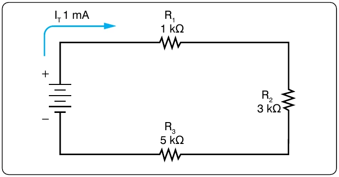
Figure 12-86 illustrates the very basic idea of Kirchhoff’s Voltage Law. There are two resistors in this example. One has a drop of 14 volts and the other has a drop of 10 volts. The source voltage must equal the sum of the voltage drops around the circuit. By inspection, it is easy to determine the source voltage as 24 volts.
Figure 12-87 shows a series circuit with three voltage drops and one voltage source rated at 24 volts. Two of the voltage drops are known. However, the third is not known. Using Kirchhoff’s Voltage Law, the third voltage drop can be determined.
With three resistors in the circuit: