
Chapter 12
Fundamentals of Electricity & Electronics
Parallel DC Circuits
A circuit in which two of more electrical resistances or loads are connected across the same voltage source is called a parallel circuit. The primary difference between the series circuit and the parallel circuit is that more than one path is provided for the current in the parallel circuit. Each of these parallel paths is called a branch. The minimum requirements for a parallel circuit are the following:
- A power source
- Conductors
- A resistance or load for each current path
- Two or more paths for current flow
Figure 12-96 depicts the most basic parallel circuit. Current flowing out of the source divides at point A in the diagram and goes through R1 and R2. As more branches are added to the circuit, more paths for the source current are provided.
Voltage Drops
The first point to understand is that the voltage across any branch is equal to the voltage across all of the other branches.
Total Parallel Resistance
The parallel circuit consists of two or more resistors connected in such a way as to allow current flow to pass through all of the resistors at once. This eliminates the need for current to pass one resistor before passing through the next. When resistors are connected in parallel, the total resistance of the circuit decreases. The total resistance of a parallel combination is always less than the value of the smallest resistor in the circuit. In the series circuit, the current has to pass through the resistors one at a time. This gave a resistance to the current equal the sum of all the resistors. In the parallel circuit, the current has several resistors that it can pass through, actually reducing the total resistance of the circuit in relation to any one resistor value.
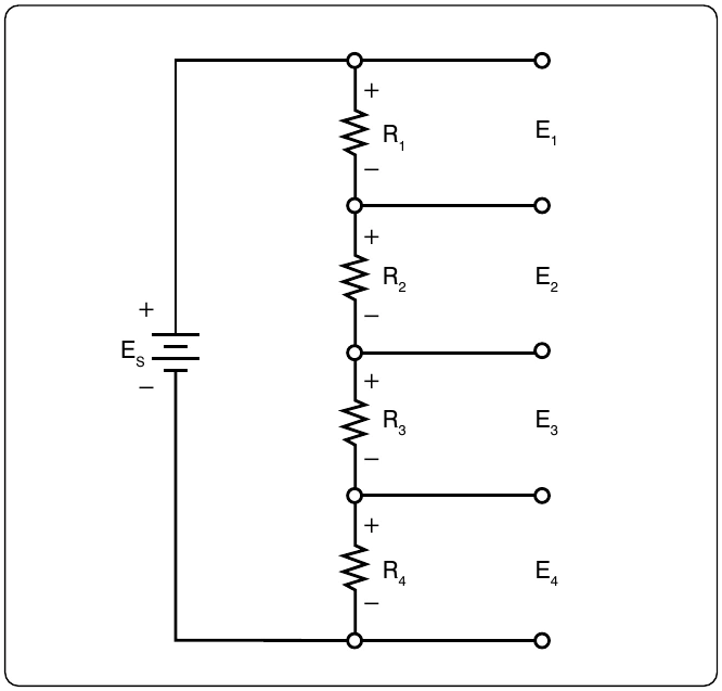
The amount of current passing through each resistor varies according to its individual resistance. The total current of the circuit is the sum of the current in all branches. It can be determined by inspection that the total current is greater than that of any given branch. Using Ohm’s Law to calculate the total resistance based on the applied voltage and the total current, it can be determined that the total resistance is less than any branch.
calculated, it still can be said that the combined resistance
Resistors in Parallel
The formula for the total parallel resistance is as follows: