
Chapter 12
Fundamentals of Electricity & Electronics
Substitute the known values:
First, the voltage drop across each of the individual resistors must be determined.
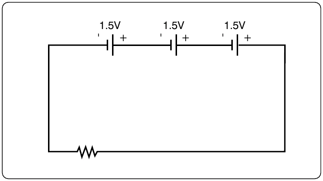
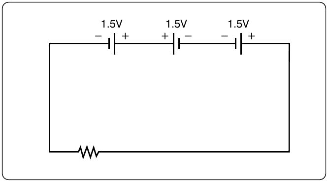
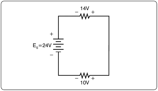
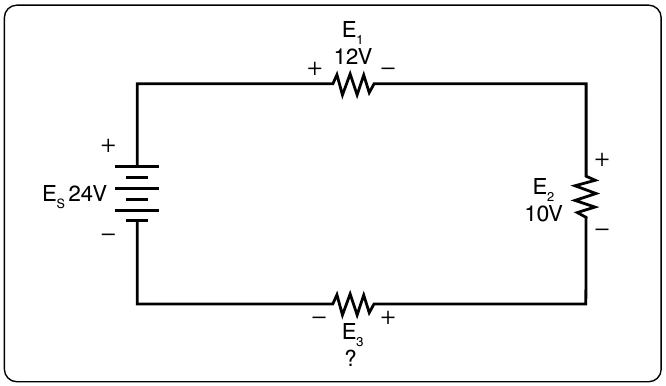
Kirchhoff’s Voltage Law is now employed to determine the voltage drop across E4.
With four resistors in the circuit
Using Ohm’s Law and substituting in E4, the value for R4 can now be determined.
Voltage Dividers
Voltage dividers are devices that make it possible to obtain more than one voltage from a single power source. A voltage divider usually consists of a resistor, or resistors connected in series, with fixed or movable contacts and two fixed terminal contacts. As current flows through the resistor, different voltages can be obtained between the contacts.
Series circuits are used for voltage dividers. The voltage divider rule allows the technician to calculate the voltage across one or a combination of series resistors without having to first calculate the current in the circuit. [Figure 12-89] Because the current flows through each resistor, the voltage drops are proportional to the ohmic values of the constituent resistors. To understand how a voltage divider works, examine Figure 12-90 carefully and observe the following:
Each load draws a given amount of current: I1, I2, I3. In addition to the load currents, some bleeder current (IB) flows. The current (IT) is drawn from the power source and is equal to the sum of all currents.
The voltage at each point is measured with respect to a common point. Note that the common point is the point at which the total current (IT) divides into separate currents (I1, I2, I3). Each part of the voltage divider has a different current flowing in it. The current distribution is as follows: