
Chapter 12
Fundamentals of Electricity & Electronics
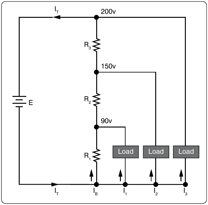
Through R1 — bleeder current (IB) Through R2 — IB + I1 Through R3 — IB + I1, + I2
The voltage across each resistor of the voltage divider is:
90 volts across R1 60 volts across R2 50 volts across R3
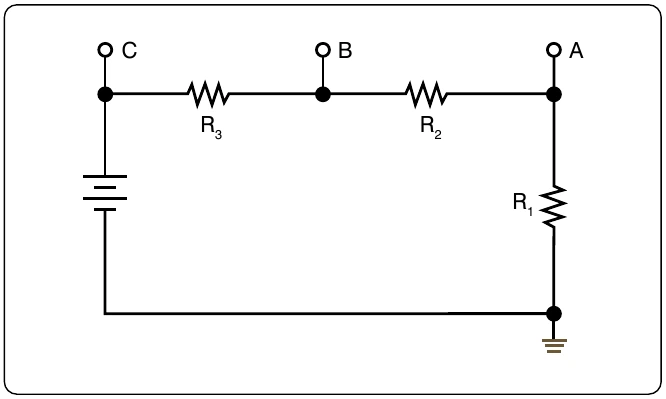
The voltage divider circuit discussed up to this point has had one side of the power supply (battery) at ground potential. In Figure 12-91, the common reference point (ground symbol) has been moved to a different point on the voltage divider. The voltage drop across R1 is 20 volts; however, since tap A is connected to a point in the circuit that is at the same potential as the negative side of the battery, the voltage between tap A and the reference point is a negative (−) 20 volts. Since resistors R2 and R3 are connected to the positive side of the battery, the voltages between the reference point and tap B or C are positive.
The following rules provide a simple method of determining negative and positive voltages: (1) If current enters a resistance flowing away from the reference point, the voltage drop across that resistance is positive in respect to the reference point; (2) if current flows out of a resistance toward the reference point, the voltage drop across that resistance is negative in respect to the reference point. It is the location of the reference point that determines whether a voltage is negative or positive.
Tracing the current flow provides a means for determining the voltage polarity. Figure 12-92 shows the same circuit with the polarities of the voltage drops and the direction of current flow indicated.
The current flows from the negative side of the battery to R1. Tap A is at the same potential as the negative terminal of the battery since the slight voltage drop caused by the resistance of the conductor is disregarded; however, 20 volts of the source voltage are required to force the current through R1 and this 20-volt drop has the polarity indicated. Stated another way, there are only 80 volts of electrical pressure left in the to move the electrons through R2, and in a similar manner the remaining 50 volts are used for R3. But the voltages across R2 and R3 are positive voltages, since they are above ground potential.
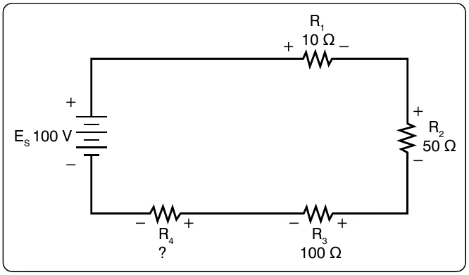
Figure 12-93 shows the voltage divider used previously. The voltage drops across the resistances are the same; however, the reference point (ground) has been changed. The voltage between ground and tap A is now a negative 100 volts, or the applied voltage.
The voltage between ground and tap B is a negative 80 volts, and the voltage between ground and tap C is a negative 50 volts.
Determining the Voltage Divider Formula
Figure 12-94 shows the example network of four resistors and a voltage source. With a few simple calculations, a formula for determining the voltage divisions in a series circuit can be determined.
The voltage drop across any particular resistor shall be called EX, where the subscript x is the value of a particular resistor (1, 2, 3, or 4). Using Ohm’s Law, the voltage drop across any As seen earlier in the handbook, the current is equal to the source voltage divided by the total resistance of the series circuit.
The current equation can now be substituted into the equation for Ohm’s Law.
)( ) ES
This equation is the general voltage divider formula. The explanation of this formula is that the voltage drop across any resistor or combination of resistors in a series circuit is equal to the ratio of the resistance value to the total resistance, divided by the value of the source voltage. Figure 12-95 illustrates this with a network of three resistors and one voltage source.