Chapter 12
Fundamentals of Electricity & Electronics
3 R 3
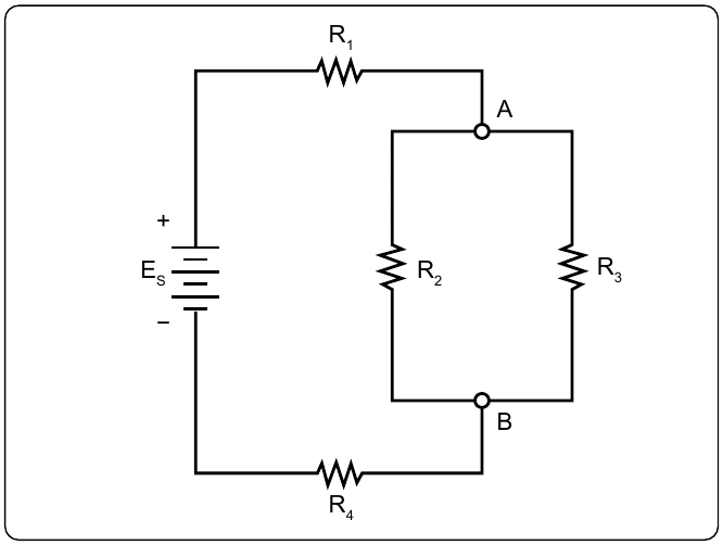
R2 and R3 can be reduced to R23. Figure 12-101 now shows an equivalent circuit with three series connected resistors. The total resistance of the circuit can now be simply determined by adding up the values of resistors R1, R23, and R4.
Determining the Total Resistance
A more quantitative example for determining total resistance and the current in each branch in a combination circuit is shown in the following example. [Figure 12-102]
The first step is to determine the current at junction A, leading into the parallel branch. To determine the IT, the total resistance RT of the entire circuit must be known. The total resistance of the circuit is given as:
) Parallel network
With the total resistance RT now determined, the total IT can be determined. Using Ohm’s Law:
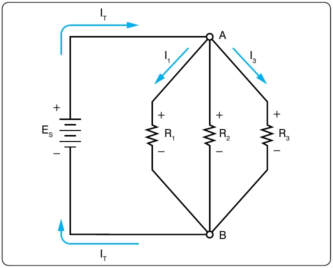
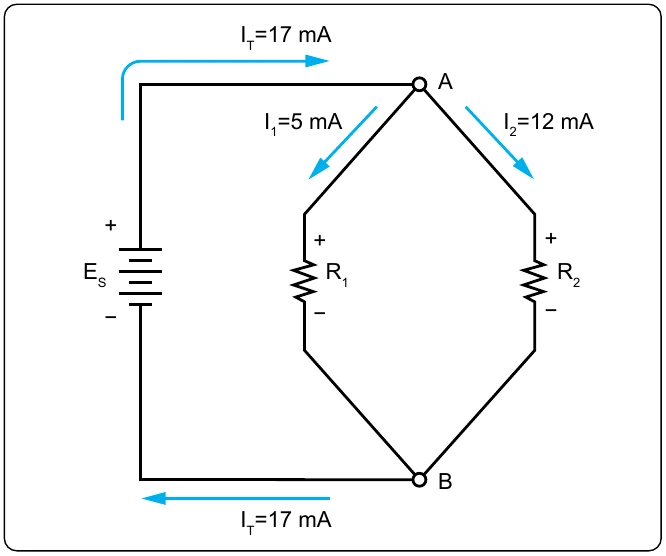
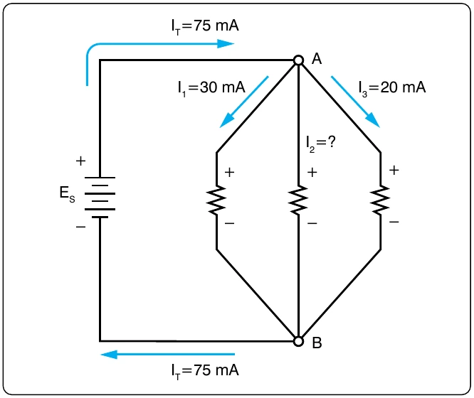
The current through the parallel branches of R2 and R3 can be determined using the current divider rule discussed earlier in this handbook.
Recall Parallel Branch Resistance:
Substitute values for I2: