
Chapter 12
Fundamentals of Electricity & Electronics
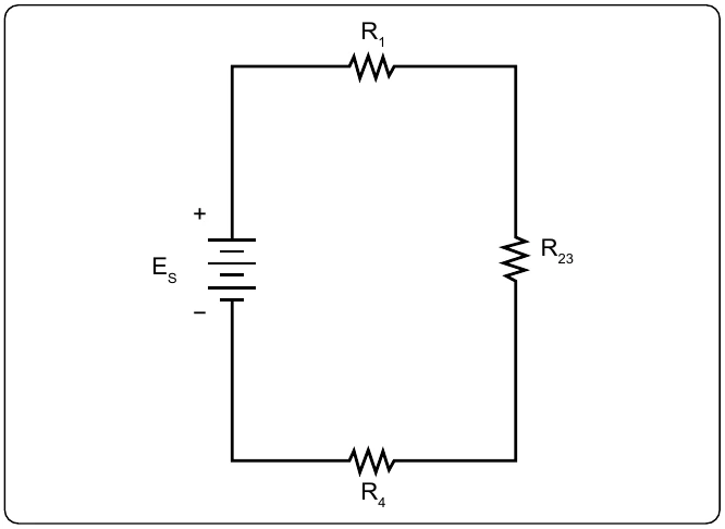
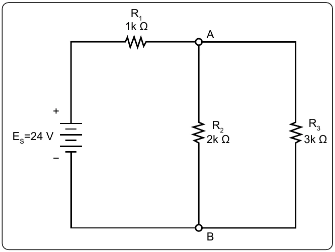
Now using Kirchhoff’s Current Law, the current in the branch with R3 can be determined.
Alternating Current (AC) & Voltage
Alternating current (AC) has largely replaced direct current (DC) in commercial power systems for a number of reasons. It can be transmitted over long distances more readily and more economically than DC, since AC voltages can be increased or decreased by means of transformers.
Because more and more units are being operated electrically in airplanes, the power requirements are such that a number of advantages can be realized by using AC. Space and weight can be saved since AC devices, especially motors, are smaller and simpler than DC devices. In most AC motors, no brushes are required, and commutation trouble at high altitude is eliminated. Circuit breakers operate satisfactorily under load at high altitudes in an AC system, whereas arcing is so excessive on DC systems that circuit breakers must be replaced frequently. Finally, most airplanes using a 24-volt DC system have special equipment that requires a certain amount of 400-cycle AC current.
AC and DC Compared
Many of the principles, characteristics, and effects of AC are similar to those of DC. Similarly, there are a number of differences. DC flows constantly in only one direction with a constant polarity. It changes magnitude only when the circuit is opened or closed, as shown in the DC waveform in Figure 12-103. AC changes direction at regular intervals, increases in value at a definite rate from zero to a maximum positive strength, and decreases back to zero; then it flows in the opposite direction, similarly increasing to a maximum negative value, and again decreasing to zero. DC and AC waveforms are compared in Figure 12-103.
Since AC constantly changes direction and intensity, the following two effects (to be discussed later) take place in AC circuits that do not occur in DC circuits:
- Inductive reactance
- Capacitive reactance
Generator Principles
After the discovery that an electric current flowing through a conductor creates a magnetic field around the conductor, there was considerable scientific speculation about whether a magnetic field could create a current flow in a conductor. In 1831, Faraday discovered that this could be accomplished.
To show how an electric current can be created by a magnetic field, a demonstration similar to Figure 12-104 can be used. Several turns of a conductor are wrapped around a cylindrical form, and the ends of the conductor are connected together to form a complete circuit, which includes a galvanometer. If a simple bar magnet is plunged into the cylinder, the galvanometer can be observed to deflect in one direction from its zero (center) position. [Figure 12-104A]
When the magnet is at rest inside the cylinder, the galvanometer shows a reading of zero, indicating that no current is flowing. [Figure 12-104B]
In Figure 12-104C, the galvanometer indicates a current flow in the opposite direction when the magnet is pulled from the cylinder.
The same results may be obtained by holding the magnet stationary and moving the cylinder over the magnet, indicating that a current flows when there is relative motion between the wire coil and the magnetic field. These results obey a law first stated by the German scientist, Heinrich Lenz. Lenz’s Law states that the induced current caused by the relative motion of a conductor and a magnetic field always flows in such a direction that its magnetic field opposes the motion.
When a conductor is moved through a magnetic field, an emf is induced in the conductor. [Figure 12-105] The direction (polarity) of the induced emf is determined by the magnetic lines of force and the direction the conductor is moved through the magnetic field. The generator left-hand rule (not to be confused with the left-hand rules used with a coil) can be used to determine the direction of the induced emf. [Figure 12-106] The left-hand rule is summed up as follows:
The first finger of the left hand is pointed in the direction of the magnetic lines of force (North to South), the thumb is pointed in the direction of movement of the conductor through the magnetic field, and the second finger points in the direction of the induced emf.