
Chapter 12
Fundamentals of Electricity & Electronics
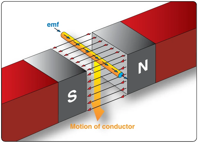
When a loop conductor is rotated in a magnetic field, a voltage is induced in each side of the loop. [Figure 12-107] The two sides cut the magnetic field in opposite directions, and although the current flow is continuous, it moves in opposite directions with respect to the two sides of the loop. If sides A and B and the loop are rotated half a turn and the sides of the conductor have exchanged positions, the induced emf in each wire reverses its direction, since the wire formerly cutting the lines of force in an upward direction is now moving downward.
The value of an induced emf depends on three factors:
- Number of wires moving through the magnetic field
- Strength of the magnetic field
- Speed of rotation
Generators of Alternating Current
Generators used to produce an alternating current are called AC generators or alternators.
The simple generator constitutes one method of generating an alternating voltage. [Figure 12-108] It consists of a rotating loop, marked A and B, placed between two magnetic poles, N and S. The ends of the loop are connected to two metal slip rings (collector rings), C1 and C2. Current is taken from the collector rings by brushes. If the loop is considered as separate wires A and B, and the left-hand rule for generators is applied, then it can be observed that as wire A moves up across the field, a voltage is induced which causes the current to flow inward. As wire B moves down across the field, a voltage is induced which causes the current to flow outward. When the wires are formed into a loop, the voltages induced in the two sides of the loop are combined. Therefore, for explanatory purposes, the action of either conductor, A or B, while rotating in the magnetic field is similar to the action of the loop.
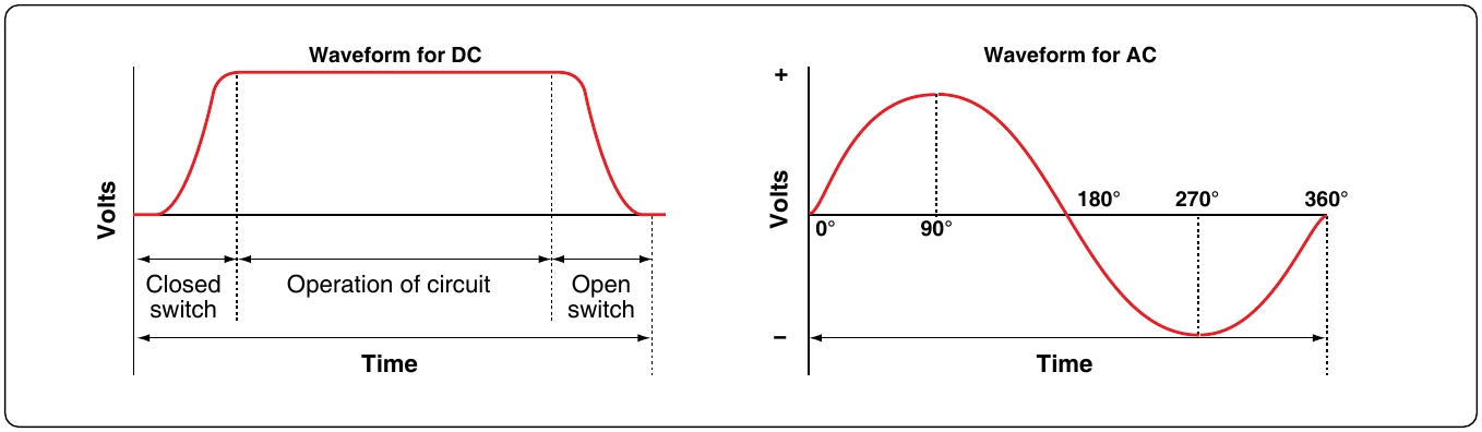
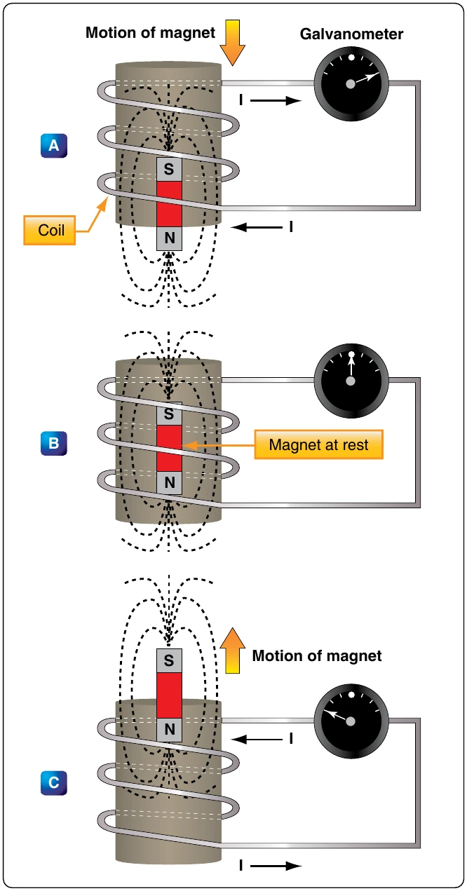
Figure 12-109 illustrates the generation of AC with a simple loop conductor rotating in a magnetic field. As it is rotated in a counterclockwise direction, varying values of voltages are induced in it.
Position 1
The conductor A moves parallel to the lines of force. Since it cuts no lines of force, the induced voltage is zero. As the conductor advances from position 1 to position 2, the voltage induced gradually increases.
Position 2
The conductor is now moving perpendicular to the flux and cuts a maximum number of lines of force; therefore, a maximum voltage is induced. As the conductor moves beyond position 2, it cuts a decreasing amount of flux at each instant, and the induced voltage decreases.
Position 3
At this point, the conductor has made one-half of a revolution and again moves parallel to the lines of force, and no voltage is induced in the conductor. As the A conductor passes position 3, the direction of induced voltage now reverses since the A conductor is moving downward, cutting flux negative direction, until it reaches position 4.
Position 4
Like position 2, the conductor is again moving perpendicular to the flux and generates a maximum negative voltage. From position 4 to 5, the induced voltage gradually decreases until the voltage is zero, and the conductor and wave are ready to start another cycle.
Position 5
The curve shown at position 5 is called a sine wave. It represents the polarity and the magnitude of the instantaneous values of the voltages generated. The horizontal base line is divided into degrees, or time, and the vertical distance above or below the base line represents the value of voltage at each particular point in the rotation of the loop.