Aviation Training Experts™

handbook

Aviation Maintenance Technician Handbook–General

FAA-H-8083-30B Version 2023

Chapter 12

Fundamentals of Electricity & Electronics
Formula: lll ; 200 ; 200 μf = = 0.000200 farads ; 1,000,000 ; 1 ; XC = ; 2πf ; C ; 1 ; XC = ; 6.28 × 60 × 0.000200 farads ; 1 ; XC = ; 0.07536
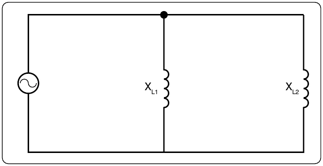
Figure 12-132. Inductances in parallel.
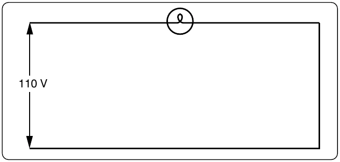
Figure 12-133. Applying DC and AC to a circuit.
Formula: llll ; EXC = I × XC ; EXC = 6.7 × 13 ; EXC = 86.1 volts
Formula: Z = R2 + XC 2 ; Z = 102 + 132 ; Z = 100 + 169 ; Z = 269 ; Z = 16.4 ohms capacitive reactance
Formula: E ; I = ; Z ; 110 ; I = ; 16.4 ; I = 6.7 amperes
Formula: ER = 6.7 × 10 ; ER = 67 volts
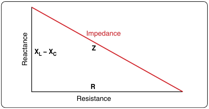
Figure 12-134. Impedance triangle.
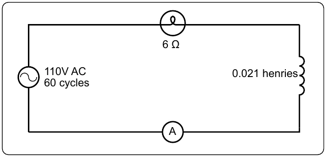
Figure 12-135. A circuit containing resistance and inductance.

applied voltage, use the following formula:

Formula: ET = (ER )2 + (EXC)2 ; ET = 672 + 86.12 ; ET = 4,489 + 7,413 ; ET = 11,902 ; ET = 110 volts

When the circuit contains resistance, inductance, and capacitance, the following equation is used to find the

Formula: impedance: ; Z = R2 + (XL – XC)2

Example: What is the impedance of a series circuit, consisting of a capacitor with a reactance of 7 ohms, an inductor with a reactance of 10 ohms, and a resistor with a resistance of 4 ohms? [Figure 12-137]

Solution:

Formula: Z = R2 + (XL – XC)2 ; Z = 42 + (10 – 7)2 ; Z = 42 + 32 ; Z = 25 ; Z = 5 ohms ; Assuming that the reactance of the capacitor is 10 ohms and ; the reactance of the inductor is 7 ohms, then XC is greater ; than XL. Thus, ; Z = R2 + (XL – XC)2 ; Z = 42 + (7 – 10)2 ; Z = 42 + (–3)2 ; Z = 16 + 9 ; Z = 25 ; Z = 5 ohms

Parallel AC Circuits

The methods used in solving parallel AC circuit problems are basically the same as those used for series AC circuits. Out of phase voltages and currents can be added by using the law of right triangles. However, in solving circuit problems, the currents through the branches are added since the voltage drops across the various branches are the same and are equal to the applied voltage. In Figure 12-138, a parallel AC circuit containing an inductance and a resistance is shown schematically. The current flowing through the inductance, IL, is 0.0584 ampere, and the current flowing through the resistance is 0.11 ampere. What is the total current in the circuit?

Solution:

Formula: IT = IL 2 + IR 2 ; = (0.0584)2 + (0.11)2 ; = 0.0155 ; = 0.1245 ampere