
Chapter 12
Fundamentals of Electricity & Electronics
The square root of both sides of the equation gives
This formula can be used to determine the impedance when the values of inductive reactance and resistance are known. It can be modified to solve for impedance in circuits containing capacitive reactance and resistance by substituting XC in the formula in place of XL. In circuits containing resistance with both inductive and capacitive reactance, the reactances can be combined, but because their effects in the circuit are exactly opposite, they are combined by subtraction:
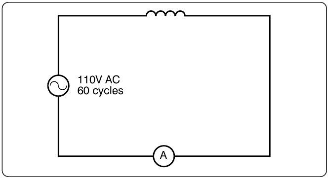
In Figure 12-135, a series circuit consisting of resistance and inductance connected in series is connected to a source of 110 volts at 60 cps. The resistive element is a lamp with 6 ohms resistance, and the inductive element is a coil with an inductance of 0.021 henry. What is the value of the impedance and the current through the lamp and the coil?
Solution:
First, the inductive reactance of the coil is computed:
Next, the total impedance is computed:
Then the current flow,
The voltage drop across the resistance (ER) is:
The voltage drop across the inductance (EXL) is:
The sum of the two voltages is greater than the impressed voltage. This results from the fact that the two voltages are out of phase and, as such, represent the maximum voltage. If the voltage in the circuit is measured by a voltmeter, it is approximately 110 volts, the impressed voltage. This can be proved by the equation: