
Chapter 12
Fundamentals of Electricity & Electronics
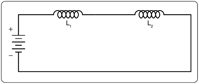
In AC series circuits, inductive reactances are added like resistances in series in a DC circuit. [Figure 12-131] Thus, the total reactance in the illustrated circuit equals the sum of the individual reactances.
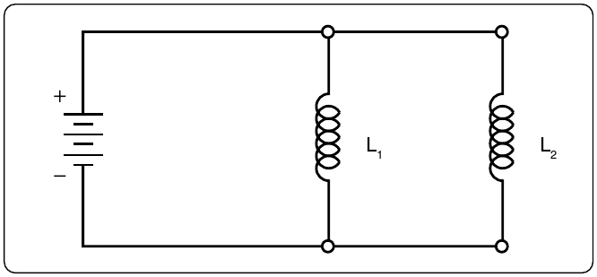
The total reactance of inductors connected in parallel is found the same way as the total resistance in a parallel circuit. [Figure 12-132] Thus, the total reactance of inductances connected in parallel, as shown, is expressed as:
AC Circuits
Ohm’s Law for AC Circuits
The rules and equations for DC circuits apply to AC circuits only when the circuits contain resistance alone, as in the case of lamps and heating elements. In order to use effective values of voltage and current in AC circuits, the effect of inductance and capacitance with resistance must be considered.
The combined effects of resistance, inductive reactance, and capacitive reactance make up the total opposition to current flow in an AC circuit. This total opposition is called impedance and is represented by the letter Z. The unit for the measurement of impedance is the ohm.
Series AC Circuits
If an AC circuit consists of resistance only, the value of the impedance is the same as the resistance, and Ohm’s Law for
ohms resistance connected across a source is illustrated. To find how much current flows if 110 volts DC is applied and how much current flows if 110 volts AC are applied, the following examples are solved:
When AC circuits contain resistance and either inductance or capacitance, the impedance, Z, is not the same as the this opposition consists of resistance and reactance, either inductive or capacitive or elements of both.
Resistance and reactance cannot be added directly, but they can be considered as two forces acting at right angles to each other. Thus, the relation between resistance, reactance, and impedance may be illustrated by a right triangle. [Figure 12-134]
Since these quantities may be related to the sides of a right triangle, the formula for finding the impedance, or total opposition to current flow in an AC circuit, can be found by using the law of right triangles. This theorem, called the Pythagorean theorem, applies to any right triangle. It states that the square of the hypotenuse is equal to the sum of the squares of the other two sides. Thus, the value of any side of a right triangle can be found if the other two sides are known. If an AC circuit contains resistance and inductance, as shown in Figure 12-135, the relation between the sides can be stated as: