
Chapter 12
Fundamentals of Electricity & Electronics
When a spring scale is used, the measurement of the pressure that a brush exerts on the commutator is read directly on the scale. The scale is applied at the point of contact between the spring arm and the top of the brush, with the brush installed in the guide. The scale is drawn up until the arm just lifts off the brush surface. At this instant, the force on the scale should be read.
Flexible low resistance pigtails are provided on most heavy current carrying brushes, and their connections should be securely made and checked at frequent intervals. The pigtails should never be permitted to alter or restrict the free motion of the brush.
The purpose of the pigtail is to conduct the current, rather than subjecting the brush spring to currents that would alter its spring action by overheating. The pigtails also eliminate any possible sparking to the brush guides caused by the movement of the brushes within the holder, thus minimizing side wear of the brush.
Carbon dust resulting from brush sanding should be thoroughly cleaned from all parts of the generators after a sanding operation. Such carbon dust has been the cause of several serious fires, as well as costly damage to the generator.
Operation over extended periods of time often results in the mica insulation between commutator bars protruding above the surface of the bars. This condition is called “high mica” and interferes with the contact of the brushes to armature has been turned on a lathe, carefully undercut the mica insulation to a depth equal to the width of the mica, or approximately 1.20 inch.
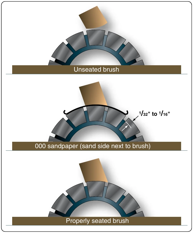
Each brush should be a specified length to work properly. If a brush is too short, the contact it makes with the commutator will be faulty, which can also reduce the spring force holding the brush in place. Most manufacturers specify the amount of wear permissible from a new brush length. When a brush has worn to the minimum length permissible, it must be replaced.
Some special generator brushes should not be replaced because of a slight grooving on the face of the brush. These grooves are normal and will appear in AC and DC generator brushes which are installed in some models of aircraft generators. These brushes have two cores made of a harder material with a higher expansion rate than the material used in the main body of the brush. Usually, the main body of the brush face rides on the commutator. However, at certain temperatures, the cores extend and wear through any film on the commutator.
DC Motors
Most devices in an airplane, from the starter [Figure 12-290] to the automatic pilot, depend upon mechanical energy furnished by DC motors. A DC motor is a rotating machine, which transforms DC energy into mechanical energy. It consists of two principal parts—a field assembly and an armature assembly. The armature is the rotating part in which current carrying wires are acted upon by the magnetic field.
Whenever a current carrying wire is placed in the field of a magnet, a force acts on the wire. The force is not one of attraction or repulsion; however, it is at right angles to the wire and also at right angles to the magnetic field set up by the magnet. The action of the force upon a current carrying wire placed in a magnetic field is shown in Figure 12-291. A wire is located between two permanent magnets. The lines of force in the magnetic field are from the North pole to the South pole. When no current flows, no force is exerted on the wire, but when current flows through the wire, a magnetic field is set up about it. [Figure 12-291] The direction of the field depends on the direction of current flow. Current in one direction creates a clockwise field about the wire, and current in the other direction, a counterclockwise field.
Since the current carrying wire produces a magnetic field, a reaction occurs between the field about the wire and the magnetic field between the magnets. When the current flows in a direction to create a counterclockwise magnetic field about the wire, this field and the field between the magnets add or reinforce at the bottom of the wire because the lines of force are in the same direction. At the top of the wire, they subtract or neutralize, since the lines of force in the two fields are opposite in direction. Thus, the resulting field at the bottom is strong and the one at the top is weak. Consequently, the wire is pushed upward. [Figure 12-291C] The wire is always pushed away from the side where the field is strongest. If current flow through the wire were reversed in direction, the two fields would add at the top and subtract at the bottom. Since a wire is always pushed away from the strong field, the wire would be pushed down.
Force Between Parallel Conductors
Two wires carrying current in the vicinity of one another exert a force on each other because of their magnetic fields. An end view of two conductors is shown in Figure 12-292. In Figure 12-292A, electron flow in both conductors is toward the reader, and the magnetic fields are clockwise around the conductors. Between the wires, the fields cancel because the directions of the two fields oppose each other. The wires are forced in the direction of the weaker field, toward each other. This force is one of attraction. In Figure 12-292B, the electron flow in the two wires is in opposite directions.
The magnetic fields are, therefore, clockwise in one and counterclockwise in the other, as shown. The fields reinforce each other between the wires, and the wires are forced in the direction of the weaker field, away from each other. This force is one of repulsion.
To summarize: conductors carrying current in the same direction tend to be drawn together; conductors carrying current in opposite directions tend to be repelled from each other.
Developing Torque
If a coil in which current is flowing is placed in a magnetic field, a force is produced which causes the coil to rotate. In the coil shown in Figure 12-293, current flows inward on side A and outward on side B. The magnetic field about B is clockwise and that about A, counterclockwise. As previously explained, a force develops which pushes side B downward. At the same time, the field of the magnets and the field about A, in which the current is inward, adds at the bottom and subtracts at the top. Therefore, A moves upward. The coil rotates until its plane is perpendicular to the magnetic lines between the North and South poles of the magnet, as indicated in Figure 12-293 by the white coil at right angles to the black coil.
The tendency of a force to produce rotation is called torque. When the steering wheel of a car is turned, torque is applied. The engine of an airplane gives torque to the propeller. Torque is developed also by the reacting magnetic fields about the current carrying coil just described. This is the torque, which turns the coil.