
Chapter 12
Fundamentals of Electricity & Electronics
Armature Assembly
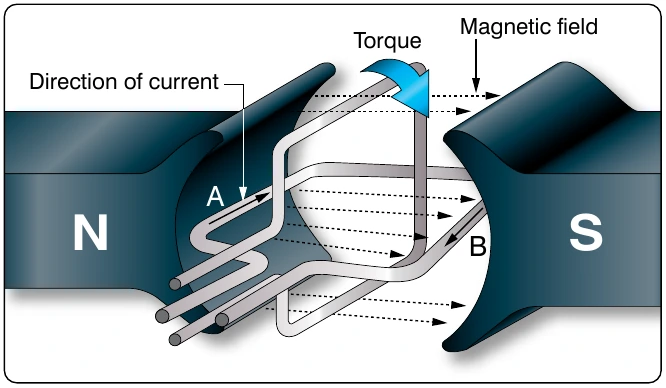
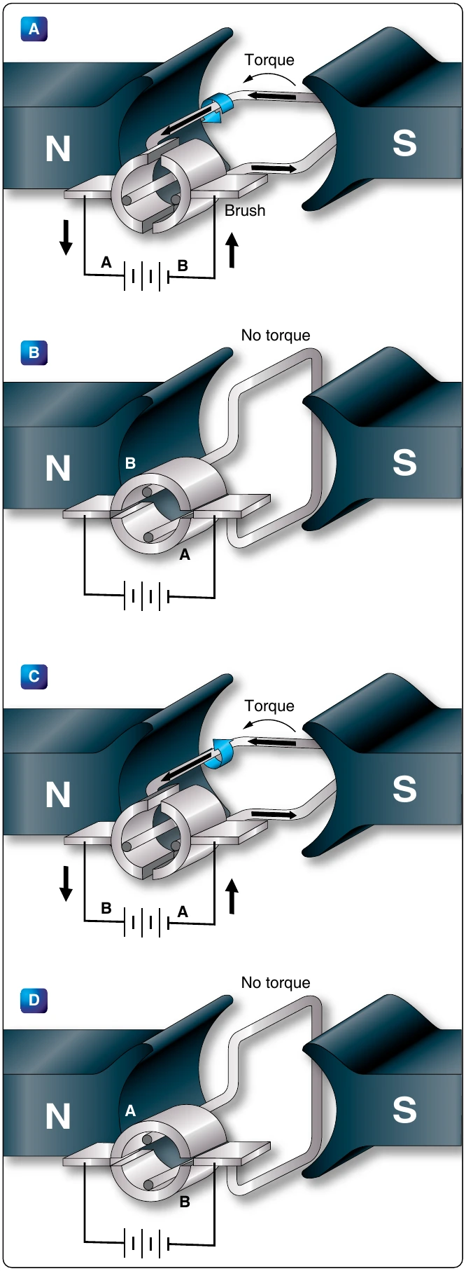
The armature assembly contains a laminated, soft-iron core, coils, and a commutator, all mounted on a rotatable steel shaft. Laminations made of stacks of soft iron, insulated from each other, form the armature core. Solid iron is not used, since a solid iron core revolving in the magnetic field would heat and use energy needlessly. The armature windings are insulated copper wire, which are inserted in slots insulated with fiber paper (fish paper) to protect the windings. The ends of the windings are connected to the commutator segments. Wedges or steel bands hold the windings in place to prevent them from flying out of the slots when the armature is rotating at high speeds. The commutator consists of a large number of copper segments insulated from each other and the armature shaft by pieces of mica. Insulated wedge rings hold the segments in place.
Field Assembly
The field assembly consists of the field frame, the pole pieces, and the field coils. The field frame is located along the inner wall of the motor housing. It contains laminated, soft-steel pole pieces on which the field coils are wound. A coil, consisting of several turns of insulated wire, fits over each pole piece and, together with the pole, constitutes a field pole. Some motors have as few as two poles, others as many as eight.
Brush Assembly
The brush assembly consists of the brushes and their holders. The brushes are usually small blocks of graphitic carbon, since this material has a long service life and also causes minimum wear to the commutator. The holders permit some play in the brushes so they can follow any irregularities in the surface of the commutator and make good contact. Springs hold the brushes firmly against the commutator. [Figure 12-298]
End Frame
The end frame is the part of the motor opposite the commutator. Usually, the end frame is designed so that it can be connected to the unit to be driven. The bearing for the drive end is also located in the end frame. Sometimes the end frame is made a part of the unit driven by the motor. When this is done, the bearing on the drive end may be located in any one of a number of places.
Types of DC Motors
There are three basic types of DC motors: series motors, shunt motors, and compound motors. They differ largely in the method in which their field and armature coils are connected.
Series DC Motor
In the series motor, the field windings, consisting of a relatively few turns of heavy wire, are connected in series with the armature winding. Both a diagrammatic and a schematic illustration of a series motor are shown in
winding also flows through the armature winding. Any increase in current, therefore, strengthens the magnetism of both the field and the armature.
Because of the low resistance in the windings, the series motor is able to draw a large current in starting. This starting current, in passing through both the field and armature windings, produces a high starting torque, which is the series motor’s principal advantage.
The speed of a series motor is dependent upon the load. Any change in load is accompanied by a substantial change in speed. A series motor runs at high speed when it has a light load and at low speed with a heavy load. If the load is removed entirely, the motor may operate at such a high speed that the armature falls apart. If high starting torque is needed under heavy load conditions, series motors have many applications. Series motors are often used in aircraft as engine starters and for raising and lowering landing gears, cowl flaps, and wing flaps.