
Chapter 12
Fundamentals of Electricity & Electronics
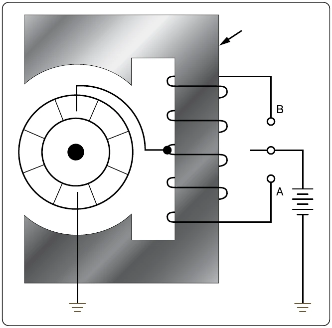
One method for reversing direction of rotation employs two field windings wound in opposite directions on the same pole. This type of motor is called a split field motor. [Figure 12-303] The single pole, double throw switch makes it possible to direct current through either of the two windings. When the switch is placed in the lower position, current flows through the lower field winding, creating a North pole at the lower field winding and at the lower pole piece, and a South pole at the upper pole piece. When the switch is placed in the upper position, current flows through the upper field winding, the magnetism of the field is reversed, and the armature rotates in the opposite direction. Some split field motors are built with two separate field windings wound on alternate poles. The armature in such a motor, a four pole reversible motor, rotates in one direction when current flows through the windings of one set of opposite pole pieces, and in the opposite direction when current flows through the other set of windings.
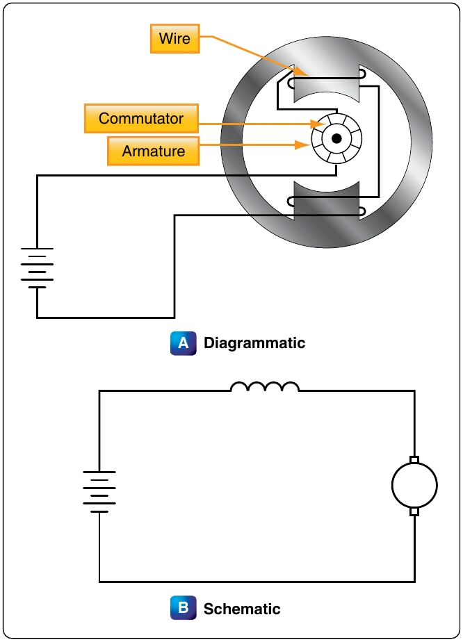
Another method of direction reversal, called the switch method, employs a double pole, double throw switch which changes the direction of current flow in either the armature or the field. In the illustration of the switch method shown in Figure 12-304, current direction may be reversed through the field but not through the armature. When the switch is thrown to the “up” position, current flows through the field winding to establish a North pole at the right side of the motor and a South pole at the left side of the motor. When the switch is thrown to the “down” position, this polarity is reversed and the armature rotates in the opposite direction.
Motor Speed
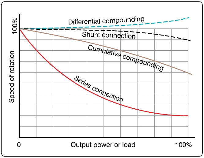
Motor speed can be controlled by varying the current in the field windings. When the amount of current flowing through the field windings is increased, the field strength increases, but the motor slows down since a greater amount of counter EMF is generated in the armature windings. When the field current is decreased, the field strength decreases, and the motor speeds up because the counter EMF is reduced. A motor in which speed can be controlled is called a variable speed motor. It may be either a shunt or series motor.
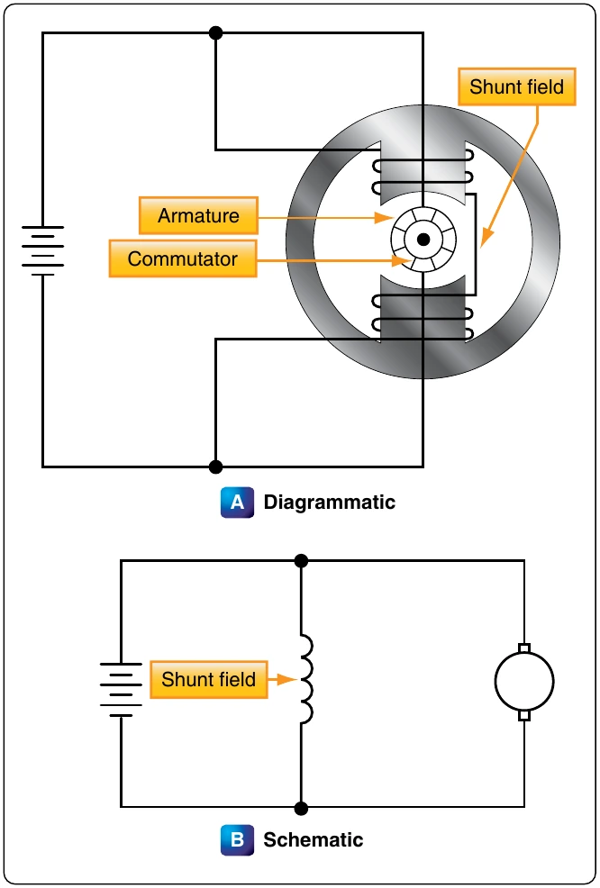
In the shunt motor, speed is controlled by a rheostat in series with the field windings. [Figure 12-305] The speed depends on the amount of current that flows through the rheostat to the field windings. To increase the motor speed, the resistance in the rheostat is increased, which decreases the field current. As a result, there is a decrease in the strength of the magnetic field and in the counter EMF. This momentarily increases the armature current and the torque. The motor then automatically speeds up until the counter EMF increases and causes the armature current to decrease to its former value. When this occurs, the motor operates at a higher fixed speed than before.
To decrease the motor speed, the resistance of the rheostat is decreased. More current flows through the field windings and increases the strength of the field; then, the counter EMF increases momentarily and decreases the armature current. As a result, the torque decreases and the motor slows down until the counter EMF decreases to its former value; then the motor operates at a lower fixed speed than before.
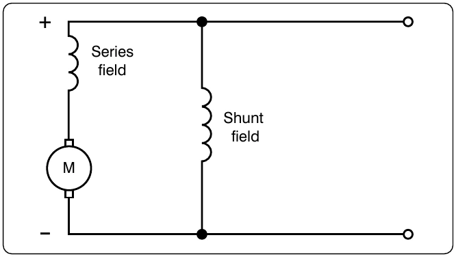
In the series motor, the rheostat speed control is connected either in parallel or in series with the motor field, or in parallel with the armature. When the rheostat is set for maximum resistance, the motor speed is increased in the parallel armature connection by a decrease in current. When the rheostat resistance is maximum in the series connection, motor speed is reduced by a reduction in voltage across the motor. For above normal speed operation, the rheostat is in Losses occur when electrical energy is converted to mechanical energy (in the motor), or mechanical energy is converted to electrical energy (in the generator). For the machine to be efficient, these losses must be kept to a minimum. Some losses are electrical; others are mechanical. Electrical losses are classified as copper losses and iron losses; mechanical losses occur in overcoming the friction of various parts of the machine.
Copper losses occur when electrons are forced through the copper windings of the armature and the field. These losses are proportional to the square of the current. They are sometimes called I2R losses, since they are due to the power dissipated in the form of heat in the resistance of the field and armature windings.
Iron losses are subdivided in hysteresis and eddy current losses. Hysteresis losses are caused by the armature revolving in an alternating magnetic field. It, therefore, becomes magnetized first in one direction and then in the other. The residual magnetism of the iron or steel of which the armature is made causes these losses. Since the field magnets are always magnetized in one direction (DC field), they have no hysteresis losses.
Eddy current losses occur because the iron core of the armature is a conductor revolving in a magnetic field. This sets up an EMF across portions of the core, causing currents to flow within the core. These currents heat the core and, if they become excessive, may damage the windings. As far as the output is concerned, the power consumed by eddy currents is a loss. To reduce eddy currents to a minimum, a laminated core usually is used. A laminated core is made of thin sheets of iron electrically insulated from each other. The insulation between laminations reduces eddy currents, because it is “transverse” to the direction in which these currents tend to flow. However, it has no effect on the magnetic circuit. The thinner the laminations, the more effectively this method reduces eddy current losses.
Inspection and Maintenance of DC Motors
Use the following procedures to make inspection and maintenance checks:
- Check the operation of the unit driven by the motor in accordance with the instructions covering the specific installation.
- Check all wiring, connections, terminals, fuses, and switches for general condition and security.
- Keep motors clean and mounting bolts tight.
- Check brushes for condition, length, and spring tension. Minimum brush lengths, correct spring tension, and procedures for replacing brushes are given in the applicable manufacturer’s instructions.
- Inspect commutator for cleanness, pitting, scoring, roughness, corrosion, or burning. Check for high mica (IF the copper wears down below the mica, the mica insulates the brushes from the commutator.) Clean dirty commutators with a cloth moistened with the recommended cleaning solvent. Polish rough or corroded commutators with fine sandpaper (000 or finer) and blow out with compressed air. Never use emery paper since it contains metallic particles
that may cause shorts. Replace the motor if the commutator is burned, badly pitted, grooved, or worn to the extent that the mica insulation is flush with the commutator surface.
- Inspect all exposed wiring for evidence of overheating. Replace the motor if the insulation on leads or windings is burned, cracked, or brittle.
- Lubricate only if called for by the manufacturer’s instructions covering the motor. Most motors used in today’s airplanes require no lubrication between overhauls.
- Adjust and lubricate the gearbox, or unit which the motor drives, in accordance with the applicable manufacturer’s instructions covering the unit.